


SOFTWARE SETUP MANUAL
DIGITAL AUDIO PROCESSOR
DP-K1
(Version 1.05)
Thank you for purchasing TOA's Digital Audio Processor.
Please carefully follow the instructions in this manual to ensure long, trouble-free use of your equipment.
[Instruction manual configuration]
Operating Instructions
(separately attached)
Describes how to operate, install, and connect the DP-K1.
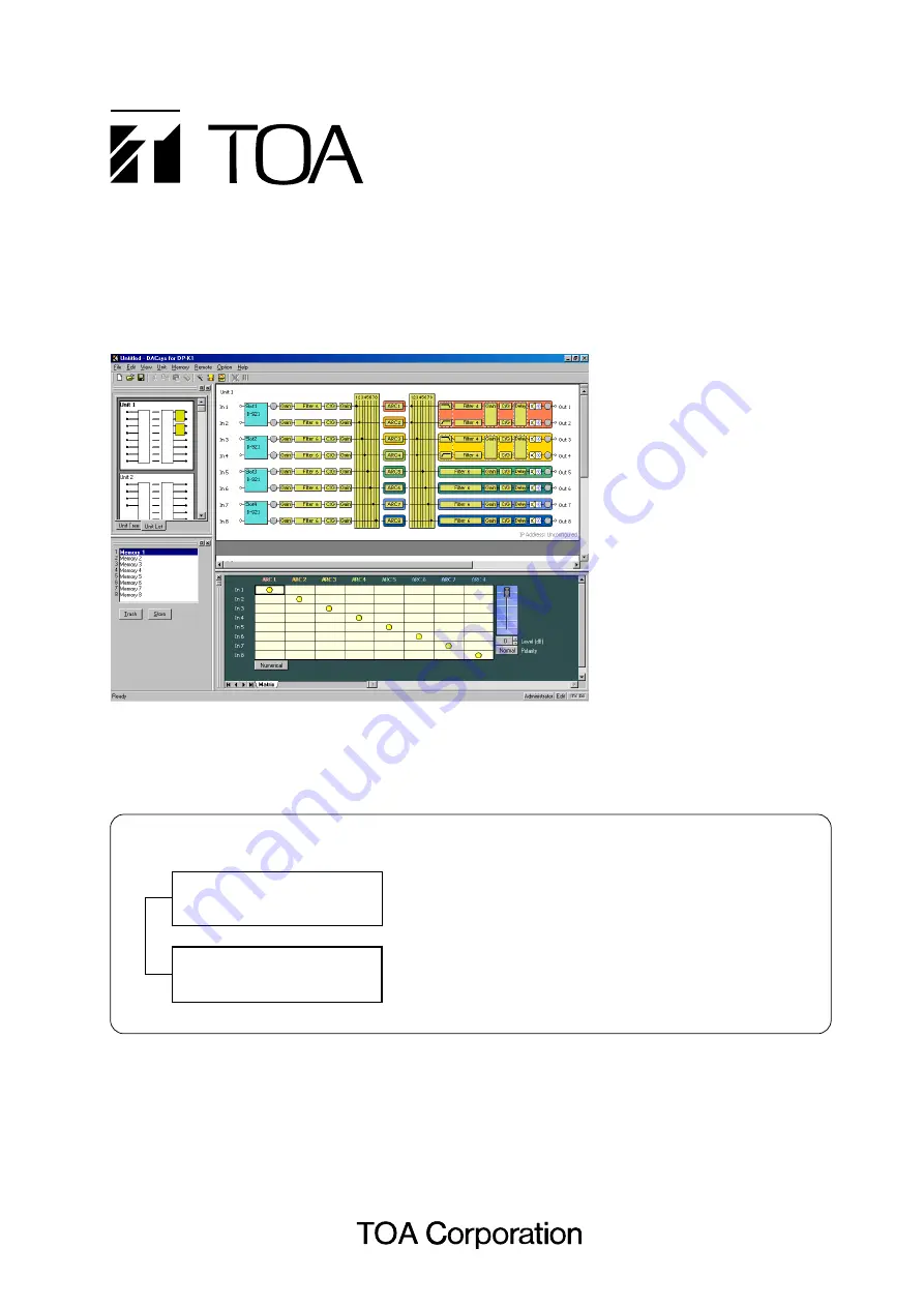
Software Setup Manual
(this document)
Describes the details of signal processing functions and
how to set the functions using the setting software, and
update the firmware.
This book supports the following
software versions.
Firmware:
Version 2.00 or later
DP-K1 setting software:
Version 2.00 or later
Summary of Contents for DP-K1
Page 102: ...200705 URL http www toa jp...


