


December 14th 2018
www.thonk.co.uk
1
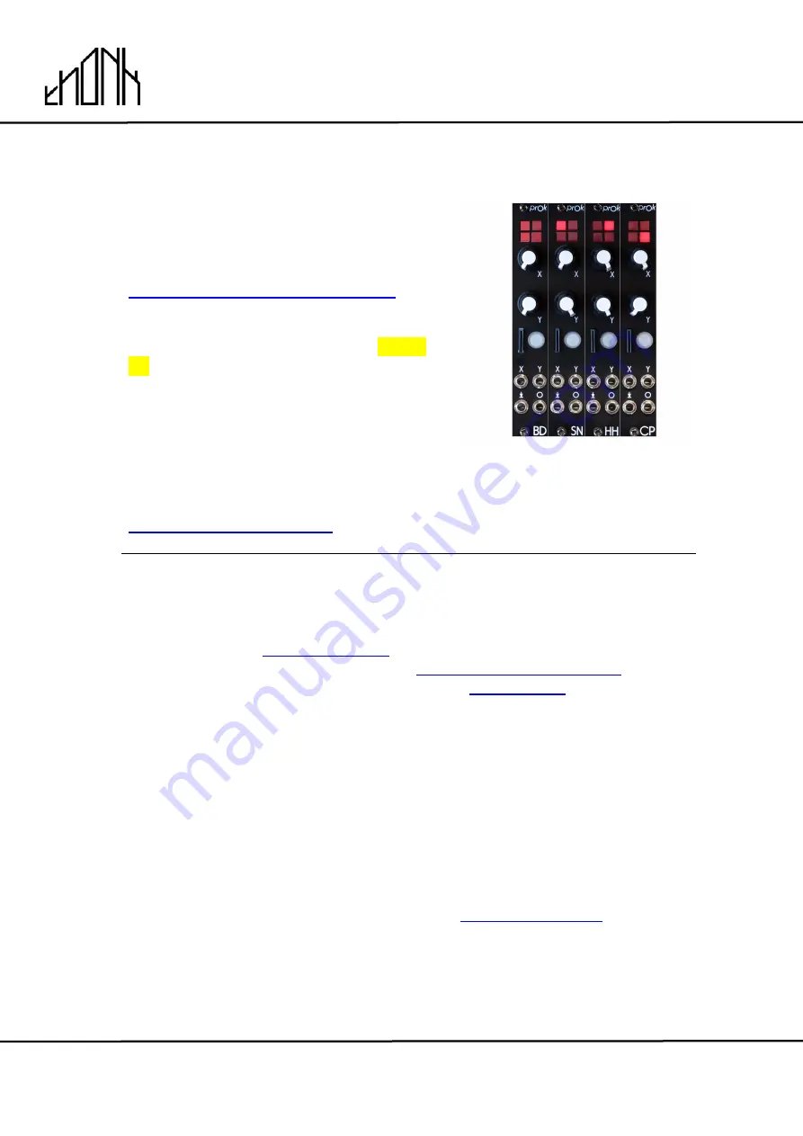
PROK DRUMS
Eurorack DIY Kit
Instructions
Version 1
OVERVIEW
For the most recent version of this
document please visit
https://thonk.co.uk/documents/prok/
This document has hi-res images. ZOOM
IN for a closer look
All Thonk kits are sold under our standard Terms and Conditions -
http://www.thonk.co.uk/faq/
DIY INSTRUCTIONS
This document gives detailed instructions that assume you have purchased a
complete kit from
www.thonk.co.uk
. It also assumes no previous knowledge
of electronics. To learn to solder try
http://youtu.be/I_NU2ruzyc4
and the
Adafruit guide to excellent soldering
– http://
bit.ly/1l77tF4
Watch and understand that whole YouTube video! If you’re not achieving the
results shown in the video then you need to buy new tools or seek advice.
You will not end up with a working module otherwise.
TOOLS REQUIRED
Soldering iron, snipe nose pliers or tweezers, masking tape, craft knife or
scalpel and diagonal cutters AKA snips AKA side-cutters. A Digital
Multimeter is always helpful for checking for bad solder joints and continuity.
Thonk sell a range of inexpensive tools here -
http://bit.ly/1jxqF3n


