THERMOROSSI POPSTAR 10, Installation, Use And Maintenance Manual
The THERMOROSSI POPSTAR 10 is a top-of-the-line heating appliance that brings both style and warmth to your home. To ensure proper installation, use, and maintenance, we highly recommend downloading our free "Installation, Use And Maintenance Manual" from manualshive.com. This comprehensive manual provides step-by-step instructions, troubleshooting tips, and everything you need to know about maximizing the functionality of your POPSTAR 10. Don't miss out - visit manualshive.com to download your manual today!
Share
Download


Reviews:
No comments
Related manuals for POPSTAR 10
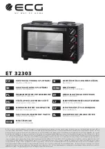
ET 32303
Brand: ECG Pages: 100

HSP 4.0-F2
Brand: HAAS + SOHN Pages: 36

Francesca 2015
Brand: Ravelli Pages: 12

ECOFIRE MEGHAN Series
Brand: Palazzetti Pages: 28

ZIRKONOFEN 700
Brand: Zirkon zahn Pages: 44

TISON
Brand: J. A. Roby Pages: 20

Nestor Martin IT33
Brand: Euroheat Pages: 32

TERMOROSSELLA PLUS EVO DSA 4.0
Brand: LA NORDICA Pages: 116

Cypress
Brand: Lopi Pages: 44

Leyden
Brand: Lopi Pages: 40

cloe
Brand: Cadel Pages: 48

KW-3530
Brand: KYOWA Pages: 3

EP24892US
Brand: Costway Pages: 5

79654
Brand: Nor-Varm Pages: 25

SURVIVOR LIFESTYLE 12-RS
Brand: England's Stove Works Pages: 9

25-PDVC
Brand: Englander Pages: 37

32-NC
Brand: England's Stove Works Pages: 37

10-CPM
Brand: Englander Pages: 42


