THERMOROSSI PELLET AIR 11, Installation, Use And Maintenance Manual
The THERMOROSSI PELLET AIR 11 is a high-quality pellet stove that offers efficient heating for any space. To ensure proper installation and operation, it is crucial to refer to the detailed "Installation, Use And Maintenance Manual". This manual is available for easy download, completely free of charge, from manualshive.com. Get the most out of your THERMOROSSI PELLET AIR 11 with this comprehensive manual.
Share
Download


Reviews:
No comments
Related manuals for PELLET AIR 11
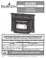
GCI60
Brand: HAMPTON BAY Pages: 18

Front-Line 55
Brand: VARDE OVNE Pages: 2

Maxx-M
Brand: Enviro Pages: 14

Denia 14
Brand: Kalor Pages: 29

001283800
Brand: Extraflame Pages: 40

S274E/EP
Brand: Century Heating Pages: 2

GBU070
Brand: Pinnacle Pages: 29

Arundel Wood PCWSB3
Brand: Portway Pages: 18

Panoramic
Brand: Portway Pages: 4

3500
Brand: Osburn Pages: 64

Enerzone BIO-45 MF
Brand: Osburn Pages: 31

CleanFire 400
Brand: Wood master Pages: 44

DEF766326
Brand: De Vielle Pages: 8

FP10056US
Brand: Costway Pages: 11

DISCOVERY-III
Brand: Quadra-Fire Pages: 20

TOSCANA 76
Brand: Drija Pages: 21

Smok DTR-AZSB-30
Brand: Moderator Pages: 45

ALTEA
Brand: Lacunza Pages: 24


