


Form: 2435-3
Arctic Installation and Operation Manual
Revision: 10
P/N 105641-01
Date: 12-1-2018
Thermal Solutions, 1175 Manheim Pike, Lancaster, PA 17601
Web:
Phone:
717-239-7642
Fax:
877-501-5212
Email:
i
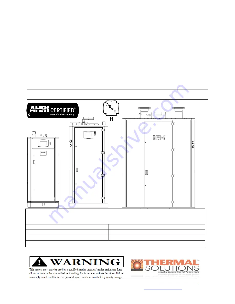
ARCTIC
High Efficiency, Low Emission
CONDENSING BOILER
INSTALLATION & OPERATION MANUAL
For service and repair to the boiler, call your heating contractor. When seeking information on
the boiler from the manufacturer, provide boiler model and serial number as shown on the rating
label.
Boiler Model:
Serial Number:
Installation Date:
Type System:
Heating Contractor:
Phone/Email:
Address:


