background image

1

SLAU595B – October 2014 – Revised January 2017

Submit Documentation Feedback

Copyright © 2014–2017, Texas Instruments Incorporated

MSP430FR4133 LaunchPad™ Development Kit (MSP

EXP430FR4133)

User's Guide

SLAU595B – October 2014 – Revised January 2017

MSP430FR4133 LaunchPad™ Development Kit

(MSP

‑‑

EXP430FR4133)

The

MSP-EXP430FR4133

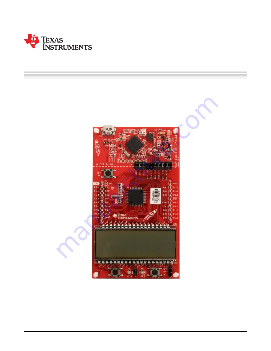
LaunchPad™ Development Kit is an easy-to-use evaluation module (EVM) for

the

MSP430FR4133

microcontroller (see

Figure 1

). It contains everything needed to start developing on

the MSP430™ ultra-low-power (ULP) FRAM-based microcontroller (MCU) platform, including on-board
emulation for programming, debugging, and energy measurements. The board features on-board buttons
and LEDs for quick integration of a simple user interface and a liquid crystal display (LCD) that showcases
the integrated driver with flexible software-configurable pins.

Figure 1. MSP-EXP430FR4133

Summary of Contents for LaunchPad MSP-EXP430FR4133

Page 1: ...pment Kit is an easy to use evaluation module EVM for the MSP430FR4133 microcontroller see Figure 1 It contains everything needed to start developing on the MSP430 ultra low power ULP FRAM based microcontroller MCU platform including on board emulation for programming debugging and energy measurements The board features on board buttons and LEDs for quick integration of a simple user interface and...

Page 2: ...FR4133 Power Block Diagram 14 10 LaunchPad to BoosterPack Connector Pinout 16 11 Programming the LaunchPad With Program Batch Files 18 12 Directing the Project Import Function to the Demo Project 19 13 When CCS Has Found the Project 20 14 MSP EXP430FR4133 Software Examples in TI Resource Explorer 23 15 Schematics 1 of 6 25 16 Schematics 2 of 6 26 17 Schematics 3 of 6 27 18 Schematics 4 of 6 28 19 ...

Page 3: ...BoosterPack Plug in Module headers which support a wide range of available BoosterPacks You can quickly add features like wireless connectivity graphical displays environmental sensing and much more Design your own BoosterPack or choose among many already available from TI and third party developers Free software development tools are also available including TI s Eclipse based Code Composer Studi...

Page 4: ...tch continues running in the background Timer Stopped S1 Start time S2 Reset time Timer Running S1 Stop time S2 Split time lap time 1 4 2 2 Temperature Mode This mode provides a simple thermometer application Using the on chip temperature sensor the temperature is displayed on the LCD S1 Pause current temperature S2 Toggle temperature between F and C 1 5 Next Steps Looking Into the Provided Code A...

Page 5: ... RXD TXD Spy Bi Wire debug SBWTDIO SBWTCK Power 5V 3V3 and GND 20 pin BoosterPack plug in module connector J1 and J2 Button Switch S2 User LEDs LED1 LED2 Button Switch S1 Segmented LCD Display 6 alphanumeric characters 6 symbols for various applications Ultra low power display MSP430FR4133 Microcontroller MSP1 Reset www ti com Hardware 5 SLAU595B October 2014 Revised January 2017 Submit Documentat...

Page 6: ...opment Kit MSP EXP430FR4133 2 1 Block Diagram Figure 3 shows the block diagram Figure 3 Block Diagram 2 2 Hardware Features 2 2 1 MSP430FR4133 The MSP430FR4133 is the next device in TI s new ULP FRAM technology platform FRAM is a cutting edge memory technology combining the best features of flash and RAM into one nonvolatile memory Device features include 1 8 V to 3 6 V operation Up to 16 MHz syst...

Page 7: ...2 6 L30 P2 5 L29 P2 4 L28 P2 3 L27 P2 2 L26 P2 1 L25 P2 0 L24 P6 7 L23 P6 6 L22 P6 5 L21 P6 4 L20 P6 3 L19 P6 2 L18 P6 1 L17 P6 0 L16 P3 7 L15 P3 6 L14 P3 5 L13 P3 4 L12 P3 3 L11 P3 2 L10 P3 1 L9 P3 0 L8 P7 7 L7 P7 6 L6 P7 5 L5 P7 4 L4 P7 3 L3 P7 2 L2 P7 1 L1 P7 0 L0 1 2 3 4 5 6 7 8 9 10 11 12 13 14 15 16 17 18 19 20 21 22 23 24 25 26 27 28 29 30 31 32 33 34 35 36 37 38 39 40 41 42 43 44 45 46 47 ...

Page 8: ...gy Feature EnergyTrace Technology EnergyTrace Technology Current Monitoring CPU State Peripheral and System State Devices Supported All MSP430 MCUs MSP430FR59xx and MSP430FR69xx MCUs Development Tool Required MSP FET or eZ FET MSP FET or eZ FET The eZ FET also provides a backchannel UART over USB connection with the host which can be very useful during debugging and for easy communication with a P...

Page 9: ...T interface of the eZ FET so that it can be used for devices other than the onboard MCU Table 2 Isolation Block Connections Jumper Description GND Ground 5V 5 V VBUS from USB 3V3 3 3 V rail derived from VBUS by an LDO in the eZ FET domain RTS Backchannel UART Ready To Send for hardware flow control The target can use this to indicate whether it is ready to receive data from the host PC The arrows ...

Page 10: ...rfaces GUIs and other programs on the PC that communicate with the LaunchPad The pathway of the backchannel UART is shown in Figure 6 The backchannel UART is the UART on eUSCI_A0 Because of USCI limitations this UART channel is shared with the UART on the 20 pin BoosterPack connector eUSCI_A0 This UART channel is also shared with the red LED on P1 0 This is a lot of sharing but all 64 pins of the ...

Page 11: ...t the PC application configures the baud rate to be the same as what is configured on the eUSCI_A0 The eZ FET also supports hardware flow control if desired Hardware flow control CTS and RTS handshaking allows the target MSP430FR4133 and the emulator to tell each other to wait before sending more data At low baud rates and with simple target applications flow control may not be necessary Applicati...

Page 12: ...s Table 3 LCD FH 1138P Segment Mapping Pin COM3 COM2 COM1 COM0 1 A1E A1F A1G A1M 2 A1A A1B A1C A1D 3 A1Q NEG A1N A1DP 4 A1H A1J A1K A1P 5 A2E A2F A2G A2M 6 A2A A2B A2C A2D 7 A2Q A2COL A2N A2DP 8 A2H A2J A2K A2P 9 A3R A3F A3G A3M 10 A3A A3B A3C A3D 11 A3Q ANT A3N A3DP 12 A3H A3J A3K A3P 13 A4R A4F A4G A4M 14 A4A A4B A4C A4D 15 A4Q A4COL A4N A4DP 16 A4H A4J A4K A4P 17 A5E A5F A5G A5M 18 A5A A5B A5C ...

Page 13: ...f use in software This allows for a single 16 bit memory access to control the whole character as opposed to split memory regions requiring separate memory accesses Table 4 LCD to MSP430 Connections LCDMEM Port Pin FR4133 Pin LCD Pin COM3 COM2 COM1 COM0 Port Pin FR4133 Pin LCD Pin COM3 COM2 COM1 COM0 LCDM19 P5 7 L39 38 A6H A6J A6K A6P P5 6 L38 37 A6Q TX A6N RX LCDM18 P5 5 L37 36 A6A A6B A6C A6D P5...

Page 14: ...uding through the on board eZ FET and from external or BoosterPack power see Figure 9 Figure 9 MSP EXP430FR4133 Power Block Diagram 2 3 1 eZ FET USB Power The most common power supply scenario is from USB through the eZ FET debugger This provides 5 V power from the USB and also regulates this power rail to 3 3 V for eZ FET operation and 3 3 V to the target side of the LaunchPad Power from the eZ F...

Page 15: ...ance 2 5 Clocking The MSP EXP430FR4133 provides an external clock in addition to the internal clocks in the device Y1 a 32 kHz crystal The 32 kHz crystal allows for lower LPM3 sleep currents than do the other low frequency clock sources Therefore the presence of the crystal allows the full range of low power modes to be used The internal clocks in the device default to the following configuration ...

Page 16: ...ad and BoosterPack tools across the TI ecosystem The 20 pin standard is compatible with the 40 pin standard that is used by other LaunchPads like the MSP EXP430F5529LP This allows some subset of functionality of 40 pin BoosterPacks to be used with 20 pin LaunchPads While most BoosterPacks are compliant with the standard some are not The MSP EXP430FR4133 LaunchPad is compatible with all 20 pin Boos...

Page 17: ...ease Rev 1 1 Added CE marking to silkscreen for compliance No functional or layout change 3 Software Examples The software examples included with the MSP430FR4133 LaunchPad can be found in the MSP EXP430FR4133 Software Examples Table 6 Software Examples Demo Name BoosterPack Required Description Details OutOfBox_FR4133 None The out of box demo pre programmed on the LaunchPad from the factory Demon...

Page 18: ...y MSP430DRIVERLIB a foundational MSP430 software library that is useful for interfacing with all MSP430 core functions and peripherals especially clocks and power Graphics library MSP430 GRLIB a library for interfacing MSP430 devices to dot matrix LCD displays Contains primitives for simple drawing as well as images and more Capacitive Touch Library CAPSENSELIBRARY a library for capacitive touch s...

Page 19: ...e directory chosen use Project Import Existing CCS Eclipse Project Direct it to the desired demo project directory that contains main c see Figure 12 Selecting the CCS subdirectory also works The CCS specific files are located there Figure 12 Directing the Project Import Function to the Demo Project When you click OK CCS should recognize the project and allow you to import it The indication that C...

Page 20: ...ace information is contained within this file The subdirectory also has an ewp project file This file can be opened into an existing workspace by clicking Project Add Existing Project Although the software examples have all of the code required to run them IAR users may download and install MSP430Ware which contains MSP430 libraries and the TI Resource Explorer These are already included in a CCS ...

Page 21: ...rst hour Press the S1 button to start the stopwatch timer counts up While the timer is running the MSP430FR4133 sleeps and wakes between LPM3 waiting for RTC interrupt and active mode incrementing calendar and updating LCD Press the S1 button again to stop the stopwatch timer and return the MSP430FR4133 back to LPM3 5 to conserve power When the stopwatch timer is stopped press the S2 button resets...

Page 22: ...ks timers ADC and so on Device specific data sheet MSP430FR413x Mixed Signal Microcontrollers data sheet SLAS865 Device specific information and all parametric information for this device 4 3 Download CCS or IAR Although the files can be viewed with any text editor more can be done with the projects if they re opened with a development environment like Code Composer Studio CCS or IAR Embedded Work...

Page 23: ...erals ADC12 Timer_A eUSCI and so on These do not use driver library rather they access the MSP430 registers directly Every MSP430 derivative has a set of these code examples When writing code that uses a peripheral they can often serve as a starting point Code examples can be accessed directly through MSP430Ware and the TI Resource Explorer without downloading the code examples mentioned above TI ...

Page 24: ...f the hardware flow control lines especially for higher baud rates Q So the onboard emulator is really open source And I can build my own onboard emulator A Yes We encourage you to do so The design files are on ti com Q The MSP430 G2 LaunchPad had a socket allowing me change the target device Why doesn t this LaunchPad use one A This LaunchPad provides more functionality and this means using a dev...

Page 25: ... 2 3 4 5 6 A B C D 1 2 3 4 5 6 Copyright 2017 Texas Instruments Incorporated www ti com Schematics 25 SLAU595B October 2014 Revised January 2017 Submit Documentation Feedback Copyright 2014 2017 Texas Instruments Incorporated MSP430FR4133 LaunchPad Development Kit MSP EXP430FR4133 6 Schematics The following figures show the schematics for the MSP EXP430FR4133 Figure 15 Schematics 1 of 6 ...

Page 26: ...9 P3 6 L14 50 P3 5 L13 51 P3 4 L12 52 P3 3 L11 53 P3 2 L10 54 P3 1 L9 55 P3 0 L8 56 P7 7 L7 57 P7 6 L6 58 P7 5 L5 59 P7 4 L4 60 P7 3 L3 61 P7 2 L2 62 P7 1 L1 63 P7 0 L0 64 MSP1 MSP430FR4x 1 2 3 4 5 6 7 8 9 10 11 12 13 14 15 16 17 18 19 20 21 22 23 24 25 26 27 28 29 30 31 32 33 34 35 36 37 38 LCD1 C3 C2 C1 C4 C5 C6 C7 C8 Y1 L 0 39 L0 L0 L1 L1 L2 L2 L4 L4 L5 L5 L6 L6 L7 L7 L8 L8 L9 L9 L10 L10 L11 L1...

Page 27: ... R5 C10 1 3 4 2 S1 U 2 U 3 U 5 U 6 1 2 3 J6 RST SBWTDIO RST SBWTDIO P2 6 P1 2 P4 0 P8 1 P1 1 RXD P2 7 P8 0 P5 1 P2 5 P8 2 P8 3 P1 6 P1 7 P5 0 P5 2 P5 3 P1 3 P1 4 P1 5 P1 0 TXD P1 0 TXD 5V Texas Instruments Mike Stein 1 1 A B C D 1 2 3 4 5 6 A B C D 1 2 3 4 5 6 3V3 GND GND Copyright 2017 Texas Instruments Incorporated www ti com Schematics 27 SLAU595B October 2014 Revised January 2017 Submit Docume...

Page 28: ...11 12 13 14 15 16 8 9 TP MSP102 D102 T102 T101 D101 NO1 1 IN1 3 NO2 5 IN2 7 COM1 8 COM2 4 V 2 GND 6 IC103 R108 C126 EZFET_DCDCTEST EZFET_DCDCRST EZFET_HOSTSDA EZFET_HOSTSCL EZFET_VCC EZFET_VCC EZFET_DCDCIO0 EZFET_DCDCIO1 EZFET_VCCOUT EZFET_VCCOUT EZFET_VCCOUT EZFET_VCCOUT EZFET_VCCOUT EZFET_DCDCCAL0 EZFET_DCDCCAL1 EZFET_DCDCCAL2 EZFET_DCDCPULSE EZFET_AVCC EZFET_AVCCOUT EZFET_VBUS EZFET_VBUS EZFET_...

Page 29: ..._SBWTDIO EZFET_SBWTCK EZFET_VCCEN1 EZFET_VCCEN2 EZFET_DCDCIO0 EZFET_DCDCIO1 EZFET_RST EZFET_TCK EZFET_TMS EZFET_TDI EZFET_TDO EZFET_TEST EZFET_XT2OUT EZFET_XT2IN EZFET_V18 EZFET_VUSB EZFET_VBUS EZFET_VBUS EZFET_VBUS EZFET_PU 1 DM EZFET_PUR EZFET_PU 0 DP EZFET_VREF EZFET_VCC EZFET_VCC EZFET_VCC EZFET_DCDCTEST EZFET_DCDCRST EZFET_HOSTSDA EZFET_HOSTSCL EZFET_DCDCPULSE EZFET_AVCCOUT2ADC EZFET_UARTRXD ...

Page 30: ...N 6 OUT 3 GND 2 IC101 C105 GND EZFET_VBUS EZFET_DP EZFET_DM EZFET_DM EZFET_SHIELD EZFET_SHIELD EZFET_PU 0 DP EZFET_PU 1 DM EZFET_PUR EZFET_VCC EZFET_RST EZFET_TCK EZFET_TMS EZFET_TDI EZFET_TDO EZFET_TEST EZFET_DCDCTEST EZFET_DCDCRST Texas Instruments Mike Stein 1 1 A B C D 1 2 3 4 5 6 A B C D 1 2 3 4 5 6 Copyright 2017 Texas Instruments Incorporated Schematics www ti com 30 SLAU595B October 2014 R...

Page 31: ...t 2014 2017 Texas Instruments Incorporated Revision History Revision History NOTE Page numbers for previous revisions may differ from page numbers in the current version Changes from July 21 2015 to January 17 2017 Page Added Rev 1 1 to Table 5 Hardware Change Log 17 Updated all figures in Section 6 Schematics 25 ...

Page 32: ...other than TI b the nonconformity resulted from User s design specifications or instructions for such EVMs or improper system design or c User has not paid on time Testing and other quality control techniques are used to the extent TI deems necessary TI does not test all parameters of each EVM User s claims against TI under this Section 2 are void if User fails to notify TI of any apparent defects...

Page 33: ... These limits are designed to provide reasonable protection against harmful interference in a residential installation This equipment generates uses and can radiate radio frequency energy and if not installed and used in accordance with the instructions may cause harmful interference to radio communications However there is no guarantee that interference will not occur in a particular installation...

Page 34: ...y for convenience and should be verified by User 1 Use EVMs in a shielded room or any other test facility as defined in the notification 173 issued by Ministry of Internal Affairs and Communications on March 28 2006 based on Sub section 1 1 of Article 6 of the Ministry s Rule for Enforcement of Radio Law of Japan 2 Use EVMs only after User obtains the license of Test Radio Station as provided in R...

Page 35: ... any interfaces electronic and or mechanical between the EVM and any human body are designed with suitable isolation and means to safely limit accessible leakage currents to minimize the risk of electrical shock hazard User assumes all responsibility and liability for any improper or unsafe handling or use of the EVM by User or its employees affiliates contractors or designees 4 4 User assumes all...

Page 36: ...OR DAMAGES ARE CLAIMED THE EXISTENCE OF MORE THAN ONE CLAIM SHALL NOT ENLARGE OR EXTEND THIS LIMIT 9 Return Policy Except as otherwise provided TI does not offer any refunds returns or exchanges Furthermore no return of EVM s will be accepted if the package has been opened and no return of the EVM s will be accepted if they are damaged or otherwise not in a resalable condition If User feels it has...

Page 37: ...other than TI b the nonconformity resulted from User s design specifications or instructions for such EVMs or improper system design or c User has not paid on time Testing and other quality control techniques are used to the extent TI deems necessary TI does not test all parameters of each EVM User s claims against TI under this Section 2 are void if User fails to notify TI of any apparent defects...

Page 38: ... These limits are designed to provide reasonable protection against harmful interference in a residential installation This equipment generates uses and can radiate radio frequency energy and if not installed and used in accordance with the instructions may cause harmful interference to radio communications However there is no guarantee that interference will not occur in a particular installation...

Page 39: ...y for convenience and should be verified by User 1 Use EVMs in a shielded room or any other test facility as defined in the notification 173 issued by Ministry of Internal Affairs and Communications on March 28 2006 based on Sub section 1 1 of Article 6 of the Ministry s Rule for Enforcement of Radio Law of Japan 2 Use EVMs only after User obtains the license of Test Radio Station as provided in R...

Page 40: ... any interfaces electronic and or mechanical between the EVM and any human body are designed with suitable isolation and means to safely limit accessible leakage currents to minimize the risk of electrical shock hazard User assumes all responsibility and liability for any improper or unsafe handling or use of the EVM by User or its employees affiliates contractors or designees 4 4 User assumes all...

Page 41: ...OR DAMAGES ARE CLAIMED THE EXISTENCE OF MORE THAN ONE CLAIM SHALL NOT ENLARGE OR EXTEND THIS LIMIT 9 Return Policy Except as otherwise provided TI does not offer any refunds returns or exchanges Furthermore no return of EVM s will be accepted if the package has been opened and no return of the EVM s will be accepted if they are damaged or otherwise not in a resalable condition If User feels it has...

Page 42: ...se resources are subject to change without notice TI grants you permission to use these resources only for development of an application that uses the TI products described in the resource Other reproduction and display of these resources is prohibited No license is granted to any other TI intellectual property right or to any third party intellectual property right TI disclaims responsibility for...

Reviews: