


SWRU078A
CC1110DK Quick Start Instructions
Revision 2.0, 2007-08-23
RF/Packet Error Rate Test
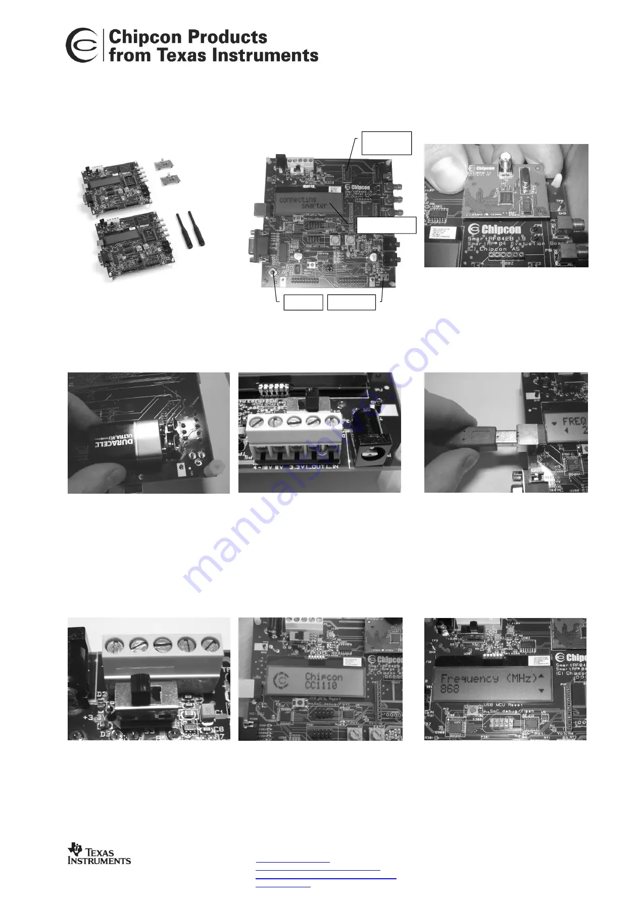
1. Kit Contents
•
2
SmartRF04EB
•
2
CC1110EM
•
2
antennas
•
2 USB cables
2. EB overview
3. Plug EM into EB
Insert a CC1110EM into both SmartRF04EBs.
The connectors will only fit in one position, so
that the EM cannot be inserted the wrong way.
Do not force the EM.
4a. Battery power
There are three different ways of applying
power to the EB:
The first method involves using a battery, either
a 9V or a 4xAA battery pack connected to the
battery connector on the bottom side of the
board
4b. DC power
The second method applies DC power using the DC
input jack (right in picture, centre is +, sleeve is
ground), or by connecting a 4-10V voltage source
between the 4-10V and 0V terminals of the power
connector (left in picture). It is also possible to
connect a 3.3V voltage source between the 3.3V and
0V terminals. The on-board voltage regulators will be
bypassed in this case.
4c. USB power
The EB can also be powered from the USB bus.
Make sure that the SmartRF
®
Studio software is
installed before connecting the EB to the PC,
otherwise you may experience problems in
installing it later due to driver issues.
Note that if multiple power sources are
connected, the source with the highest voltage
will power the EB. This means that you should
disconnect any attached battery when using a
lab supply or USB power, otherwise the battery
will be drained.
5. Set power switch
If a 3.3V source is used as described in 4b
above, the switch should be set to the leftmost
position. For all other cases, the switch should
be set to the rightmost position. This switch can
be used to turn off the EB by switching it to the
opposite position of that used to turn it on.
6. Packet error rate test
When power is applied to the board, the test
program will start. You should see the Chipcon logo
shown above on the LCD display on both EBs.
Pushing button S1 in the lower right corner of the
board will show the first menu item.
7. Select Frequency
Select frequency according to the type of EM
module in use (315 MHz, 433 MHz, 868 or 915
MHz). Move the joystick up or down to display
the choices and push button S1 in the lower
right corner of the board to select the displayed
frequency.
EM
connectors
LCD screen
Joystick
Button S1
Web sites:
http://www.ti.com/lpw
TI Worldwide Support:
http://www-k.ext.ti.com/sc/technical-
support/product-information-centers.htm
Technical Support Email:
Make sure to subscribe to the Low-Power
RF Newsletter to receive information about
updates to documentation, new product
releases and more. Sign up on our web site!
Address information


