


Web sites:
www.ti.com/lprf
E2E Forum:
www.ti.com/lprf-forum
Make sure to subscribe to the Low-Power RF
Newsletter to receive information about
updates to documentation, new product
releases, and more. Sign up on the TI web
pages.
CC2530-CC2592EM Development Kit Quick Start Guide
Opening the Box and Running the Packet Error Rate Test
1. Kit Contents
•
2 x CC2530-CC2592 EM
•
2 x 2.4GHz Antennas
•
Documentation
Caution!
The kit
contains ESD sensitive
components. Handle with
care to prevent
permanent damage.
2. Hardware Requirements
The CC2530-CC2592EM is an add-on
module that can be plugged onto a
SmartRF05EB. To run the example in this
Quick Start Guide, two SmartRF05 boards
are required to establish an RF link
between the evaluation modules.
More information about SmartRF05EB can
be found here:
www.ti.com/lit/pdf/swru210
The CC2530-CC2592EM can also be plugged
into the SmartRF05 battery boards for
standalone applications.
3. SmartRF05 Board Setup
Set the EM Selection switch in the
position SOC/TRX.
For best performance, it is recommended
to turn off the RS232 interface.
4. Power Options
There are a few ways of applying power to
the SmartRF05 board.
•
2 x 1.5V AA Alkaline Batteries
•
USB
•
External Power Supply
For the batteries and USB, there are
voltage regulators on the SmartRF05
board that will set the on-board voltage to
3.3V. The external power supply should
set a voltage that does not exceed 3.3V.
Note that there should be only one
active power source at any given time.
Select power source with jumper on header
P11:
•
Position 1-2 Batteries
•
Position 2-3 USB or DC supply.
Once P11 is set, locate P8 switch on
Smart05EB to power up the board.
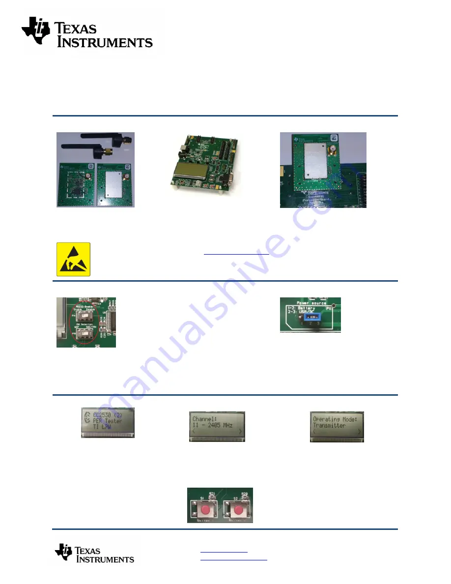
5. Packet Error Rate Setup
After power up, the preloaded PER test
application on the CC2530 will start. The
LCD will display the screen as shown in
the picture above. The number in the
parentheses is the revision of the
CC2530. Press Button S1 to enter the
menu.
Note: if you don’t see anything on the
screen make sure the board is
correctly powered (see step 5 and 6
above).
6. Select Channel
Select a channel between 11 and 26
(2405- 2480 MHz). The channel is
selected by navigating the joystick to the
right or left. Confirm the selection by
pressing Button S1.
7. Select Mode
Select receiver on one of the SmartRF05EB’s
and transmitter on the other. Use the joystick
to select mode. Confirm the selection by
pressing Button S1.


