manualshive.com logo in svg
background image

1

Loblaws Inc.,

1 President’s Choice Circle,

Brampton, Ontario

L6Y 5S5

WARNING

You must read this owner’s guide before operating 

your gas grill. Failure to follow these instructions 

could result in fire or explosion that could cause 

property damage, personal injury or death.

For your safety: This gas appliance is designed 

for outdoor use only and shall not be used in a 

building, garage or any other enclosed area.

Do not use in or on boats or recreational vehicles.

WARNING

1.  Improper installation, adjustment, alteration, 

  service or maintenance can cause injury or 

  damage to property.

2.  Read the assembly, installation, operation and 

maintenance thoroughly before assembling, 

installing, or servicing the equipment.

3.  Failure to follow these instructions could result 

in fire or explosion which could cause property 

damage, personal injury or death.

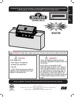
Stainless Steel 60,000BTU BBQ 

natural


gas

assembly instructions and 

owner’s guide 

MODEL NUMBER:

13 01 3008TG

SERIAL NUMBER:

natural


gas

TG3008 NG U&C-2012 FA.indd   1

12-09-26   4:36 PM

Содержание 13 01 3008TG

Страница 1: ...a Do not use in or on boats or recreational vehicles WARNING 1 Improper installation adjustment alteration service or maintenance can cause injury or damage to property 2 Read the assembly installation operation and maintenance thoroughly before assembling installing or servicing the equipment 3 Failure to follow these instructions could result in fire or explosion which could cause property damag...

Страница 2: ...ns for future reference NOTICE TO INSTALLER These instructions must be left with the owner and the owner should keep them for future reference NOTICE TO CONSUMER Retain this manual for future reference WARNING Follow all leak check procedures carefully in this manual prior to barbecue operation Do this even if the barbecue was dealer assembled Do not repair or replace any parts of the grill unless...

Страница 3: ...ng instructions 5 Avoid dangerous grease fires by cleaning out the grease cup and grease tray See instructions on page 33 6 Before opening the gas supply ensure that the lid is open burner knobs are in the off position gas is turned off and the regulator is properly attached to the tank 7 Follow the proper lighting procedure on page 31 Table of Contents General Warnings 4 Assembly Instructions 6 C...

Страница 4: ... Do not put a barbecue cover or anything flammable on or in the storage area under the barbecue or on the side shelves Keeping outdoor cooking gas appliance area clear and free from combustible materials gasoline and other flammable vapors and liquids Your gas barbecue should never be used by children Do not let children or pets play around or below the grill or in the cart Never allow children or...

Страница 5: ...aller It is recommended that an ON OFF manual shut off valve be installed at the gas supply source Outdoors after the gas line exits outside wall and before quick disconnect or before gas supply line enters ground Pipe sealing compound or pipe thread tape of the type resistant to the action of natural gas must be used on all male pipe threads Apply compound or tape to at least the first three to f...

Страница 6: ...o properly align the frame and doors assemble grill on a flat and level surface To complete your assembly you will need 1 A 2 Phillips head screw driver 2 Leak detection solution see Leak Detection section on page 30 Parts List CODE PART QTY 1 Fire Box Assembly 1 2 Warming Rack 1 3 Cooking Grill 2 4 Heat Tent 4 5 Grease Tray Assembly 1 6 Grease Cup 1 7 Side Burner Grate 1 8 Side Burner Electrode 1...

Страница 7: ...7 Parts Diagram TG3008 NG U C 2012 FA indd 7 12 09 26 4 36 PM ...

Страница 8: ...8 Hardware Reference Diagram CODE PART QTY A M6x12mm Bolt 38 B M6x8mm Bolt 4 C M5x8mm Bolt 4 D M6x40mm Bolt 2 E Washer 6 F M4x10mm Bolt 12 1 1 SCALE TG3008 NG U C 2012 FA indd 8 12 09 26 4 36 PM ...

Страница 9: ...M6x12mm Bolt on each leg A Tighten the bolts with the screwdriver STEP 2 Attach the Left Rear Leg 17 and Right Rear Leg 19 to the Bottom Shelf Assembly 26 using one M6x12mm Bolt A on each leg Tighten the bolts with the screwdriver 16 26 26 18 17 19 A x2 A x2 1 1 SCALE TG3008 NG U C 2012 FA indd 9 12 09 26 4 36 PM ...

Страница 10: ... using four M6x12mm Bolts A Tighten the bolts with the screwdriver B Attach one of the Cart Support Brackets 28 to the Right Rear Leg 19 and the Bottom Shelf Assembly 26 using two M6x12mm Bolts A Tighten the bolts with the screwdriver 22 19 19 18 28 A x4 A x2 TG3008 NG U C 2012 FA indd 10 12 09 26 4 36 PM ...

Страница 11: ... 17 using four M6x12mm Bolts A Tighten the bolts with the screwdriver B Attach the Cart Support Bracket 28 to the Left Rear Leg 17 and the Bottom Shelf Assembly 26 using two M6x12mm Bolts A Tighten the bolts with the screwdriver 21 16 17 17 28 A x4 A x2 TG3008 NG U C 2012 FA indd 11 12 09 26 4 36 PM ...

Страница 12: ... Front Leg 16 and the Right Front Leg 18 STEP 6 Attach the Bottom Skirt Front 29 on the Bottom Shelf Assembly 26 using four M4x10mm Bolts F Align the edges of the Bottom Skirt Front with the edges of the Bottom Shelf Assembly Tighten the bolts with the screwdriver 33 33 32 32 17 16 19 18 29 26 F x4 TG3008 NG U C 2012 FA indd 12 12 09 26 4 36 PM ...

Страница 13: ... edge of the Bottom Skirt Front Tighten the bolts with the screwdriver STEP 8 Attach the Bottom Skirt Left 30 to the Bottom Shelf Assembly 26 and the Bottom Skirt Front 29 using four M4x10mm Bolts F Align the edge of the Bottom Skirt Left with the front edge of the Bottom Skirt Front Tighten the bolts with the screwdriver 29 29 30 31 26 26 F x4 F x4 TG3008 NG U C 2012 FA indd 13 12 09 26 4 36 PM ...

Страница 14: ... firmly in the locked on position before continuing B Use this opportunity to make sure all the screws are tight and the frame is square because some screws may loosen during assembly STEP 11 Attach the two Door Handles 25 to the Left Front Door 23 and the Right Front Door 24 using M5x8mm Bolts C Tighten the bolts with the screwdriver 20 16 23 25 25 24 18 D x2 C x2 TG3008 NG U C 2012 FA indd 14 12...

Страница 15: ...r 24 on the right hand door post of the Bottom Skirt Front 29 D Depress the spring post on the bottom of the Door Transom 20 then align the hole in the top of the door with the spring post You should hear a click when the door is properly aligned and the door should be attached 29 29 29 29 23 24 20 20 23 24 23 24 20 20 ONLINE VIDEO STEP 12 To view a detailed video presentation for this step of the...

Страница 16: ... the Side Table Assembly 13 and the M6x12mm Bolts A Tighten the bolts with the screwdriver STEP 14 Place the Side Table Assembly 13 on the Left Rear Leg 17 and Left Front Leg 16 and attach using three M6x12mm Bolts A Tighten the bolts with the screwdriver 15 13 13 13 13 13 17 17 16 16 A x2 A x3 E x2 TG3008 NG U C 2012 FA indd 16 12 09 26 4 36 PM ...

Страница 17: ... 19 B Attach the Lighting Rod 34 to the Right Rear Leg 19 and Side Burner Assembly 9 using two M6x12mm Bolt A C Attach the Side Burner Assembly 9 to the Front Leg using one M6x12mm Bolt A Tighten the bolts with the screwdriver 9 9 9 18 18 19 19 A x2 A x1 34 TG3008 NG U C 2012 FA indd 17 12 09 26 4 36 PM ...

Страница 18: ...mbly to the Left Front Leg 16 Left Rear Leg 17 the Right Front Leg 18 and Right Rear Leg 19 using a total of four M6x12mm Bolts A Tighten the bolts with the screwdriver ONLINE VIDEO STEP 16 17 To view a detailed video presentation for this step of the assembly visit www bbqinstructions com 2013 step 16 17 or scan this QR code with a web enabled Smart Device A x4 1 16 17 16 17 19 19 18 18 TG3008 NG...

Страница 19: ...attach the Fire Box Assembly 1 to the Side Table Assembly 13 two M6x12mm Bolts A placing a Washer E between the M6x12mm Bolts A and the Fire Box Assembly 1 Tighten the bolts with the screwdriver 1 13 A x2 E x2 TG3008 NG U C 2012 FA indd 19 12 09 26 4 36 PM ...

Страница 20: ... M6x12mm Bolts A and the Fire Box Assembly 1 Tighten the bolts with the screwdriver ONLINE VIDEO STEP 16 17 To view a detailed video presentation for this step of the assembly visit www bbqinstructions com 2013 step 16 17 or scan this QR code with a web enabled Smart Device A x2 E x2 9 1 TG3008 NG U C 2012 FA indd 20 12 09 26 4 36 PM ...

Страница 21: ...IS TIME B Hang the Side Burner Control Panel 11 on the Side Burner Assembly 9 Slide the Side Burner Control Panel to the left until the Side Burner Control Panel is aligned with the edge of the Side Burner Assembly Tighten the bolts with the screwdriver 11 11 B x2 11 9 TG3008 NG U C 2012 FA indd 21 12 09 26 4 36 PM ...

Страница 22: ...ched to the Fire Box Assembly 1 C Attach the Side Burner Valve to the Side Burner Control Panel 11 using the two screws removed in the previous step ONLINE VIDEO STEP 19 To view a detailed video presentation for this step of the assembly visit www bbqinstructions com 2013 step 19 or scan this QR code with a web enabled Smart Device 10 11 TG3008 NG U C 2012 FA indd 22 12 09 26 4 36 PM ...

Страница 23: ...ner Assembly 9 IMPORTANT Make sure that the valve nozzle is properly inserted and aligned E Adust the Side Burner Control Panel 11 so that it is aligned with the front of the Main Control Panel of the Fire Box Assembly 1 Attach the Side Table Control Panel to the Fire Box Assembly using two M6x12mm Bolts A Tighten the Bolts with the screwdriver 10 10 9 9 A x2 11 TG3008 NG U C 2012 FA indd 23 12 09...

Страница 24: ...e Side Burner Electrode Wire 8 into the Side Burner Valve G Attach the Side Burner Knob 12 on the side burner control panel 11 by aligning the knob with the post and pressing firmly 8 12 TG3008 NG U C 2012 FA indd 24 12 09 26 4 36 PM ...

Страница 25: ... right until the panel is aligned with the edge of the Side Shelf Assembly Tighten the bolts with the screwdriver C Adjust the Side Table Control Panel 14 so that it is aligned with the front of the Main Control Panel of the Fire Box Assembly 1 Attach the Side Table Control Panel to the Fire Box Assembly using two M6x12mm Bolts A Tighten the bolts with the screwdriver 14 14 13 A x2 B x2 TG3008 NG ...

Страница 26: ...Side Burner Grate 7 on the Side Burner Assembly 9 and align with the holes STEP 22 Place the four Heat Tents 4 two Cooking Grills 3 and Warming Rack 2 on the Fire Box Assembly 1 9 4 3 2 TG3008 NG U C 2012 FA indd 26 12 09 26 4 36 PM ...

Страница 27: ... the back of the grill slide the Grease Tray Assembly 5 beneath the Fire Box Assembly 1 B Slide the Grease Cup 6 into the channels at the bottom of the Grease Tray Assembly 5 5 5 5 TG3008 NG U C 2012 FA indd 27 12 09 26 4 36 PM ...

Страница 28: ...t Cart Side Panel 22 Be sure that the hose does not touch the Fire Box Assembly 1 or Grease Tray 5 because they become hot during use B Attach Hose Restraint Clip 27 to the Bottom Shelf Assembly 26 using two M6x12 screws A A x2 22 27 26 1 5 TG3008 NG U C 2012 FA indd 28 12 09 26 4 36 PM ...

Страница 29: ...e Pipe Threads Quick Release Connector Hose Side Burner Valve not shown D Perform Leak Test on all fittings as found on page 30 STEP 25 Use this opportunity to make sure all the screws are tight and the frame is square because some screws may loosen during assembly STEP 26 Complete 1 2 3 4 1 2 3 4 NATURAL GAS SUPPLY TO SIDE BURNER VALVE TG3008 NG U C 2012 FA indd 29 12 09 26 4 36 PM ...

Страница 30: ...ollow these instructions could cause fire or explosion which could cause property damage personal injury or death Ensure that the barbecue is in a well ventilated area LEAK TESTING THE CONNECTIONS 1 Mix cup of liquid dishwashing soap with of a cup of water 2 Make sure control knobs are OFF FERMÉ 3 Open the gas control valve on the Natural Gas fuel line 4 Spoon the mix over the connections or use a...

Страница 31: ...d open the lid to let the gas clear for five minutes before relighting NOTE The first time you light your barbecue your barbecue may give off an odor This is normal as the barbecue burns off the manufacturing oils We recommend a trial run at a high temperature to familiarize yourself with your barbecue and to eliminate any protective substance or oil that may have been used for packing and shippin...

Страница 32: ...he grill is cool and the fuel supply is disconnected Do not clean any parts of the barbecue in a self cleaning oven The extreme heat will damage the finish Do not power wash your grill The high pressure can damage your barbecue BURNERS Your barbecue is a target for spiders and other insects They can nest in the venturi section of the burner tubes This blocks the normal gas flow and can cause the g...

Страница 33: ...llow the burner cleaning procedures CLEANING THE SIDE BURNER 1 Turn off the side burner per instructions on page 31 2 Clean the exterior of the side burner with a brass brush 3 Clear a clogged port with a straightened paper clip or steel wire Never enlarge the burner ports CAUTION Never use a toothpick to clean out the burner holes as it may break off and clog the port CLEANING THE GRILLS It is im...

Страница 34: ...R THE WINTER It is important that your barbecue is properly closed for the winter Even if you plan on grilling during the winter it is important that the grill is prepared for the winter 1 Clean the grill making sure that the grease tray and cup are cleaned 2 Wipe down the grills and racks so they are free of oil and grease The natural salts found in food can cause rusting 3 Check for any loose pa...

Страница 35: ...rn grill off by turning the fuel supply to Closed and then turn the knobs to OFF FERMÉ CAUTION When cooking indirectly meat should be placed in or over a pan so the fat and oils collects in the pan instead of dripping on to the unlit heat tents or burners Failure to do so may result in a dangerous build up of grease and oils which could ignite causing a grease fire TIPS FOR BETTER RESULTS ON YOUR ...

Страница 36: ...use tools Obstruction of gas flow Clear burner tubes Check for bent or kinked hose Spider webs or insect nest Clean venture Refer to Cleaning in venturi Burner ports clogged or blocked Clean burner ports Disengagement of burner to valve Reengage burner and valve Burners burn with a yellow or orange Inspect Spider Insect screens for Clean Spider Insect screens flame in conjunction with the possible...

Страница 37: ...heat tents salt on burners Poor alignment of valve to burner Re engage burner and valve Flame has blown out High winds Do not use barbecue in high winds Move barbecue to less windy area Flashback Fire in burner tubes Burner and or tubes are blocked Clean burners refer to Cleaning Burners Inside of lid appears to be peeling The inside of the lid is aluminum Clean thoroughly Refer to Cleaning Resemb...

Страница 38: ...38 Notes TG3008 NG U C 2012 FA indd 38 12 09 26 4 36 PM ...

Страница 39: ...39 Notes TG3008 NG U C 2012 FA indd 39 12 09 26 4 36 PM ...

Страница 40: ...ect or lack of maintenance including but not limited to damaged caused by insects within the burner tubes or grease fires as described in the manual This warranty does not cover damage caused by heat abrasive and chemical cleaners resulting in chipped porcelain enamel parts or any damage to other components used in the installation or operation of the gas grill The original consumer purchaser will...

Отзывы: