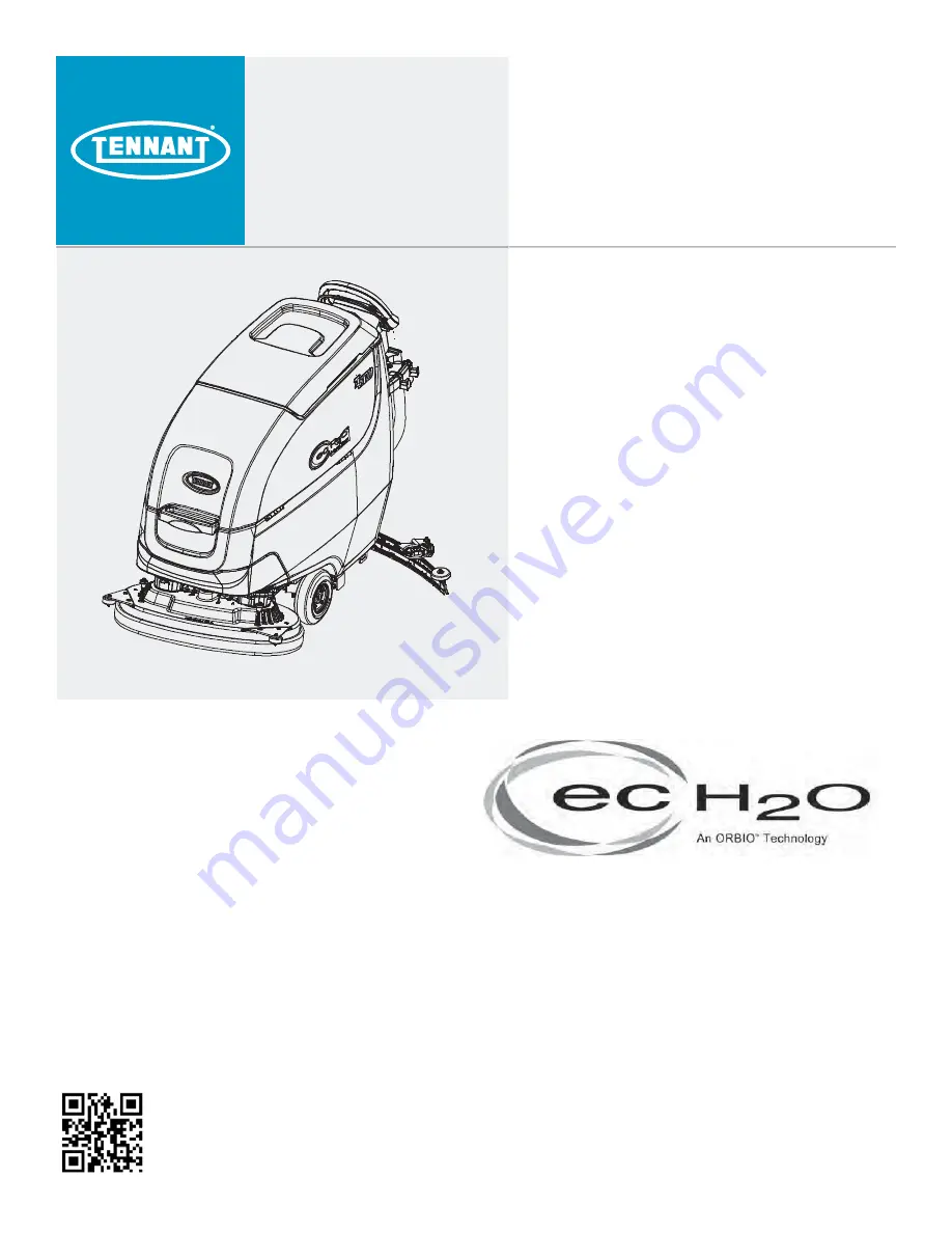
background image

T500

(Battery)

Automatic Floor Scrubber

Service Information Manual

9015504

Rev. 01 (1-2018)

*9015504*

North America / International

For the latest Parts Manuals and other 
language Operator Manuals, visit:

www.tennantco.com/manuals

Hygenic

®

 Fully Cleanable Recovery Tank

Tennant True

®

  Parts

IRIS

®

  a Tennant Technology

Pro-Panel™  Controls
Insta-Fit™ Adapter
Smart-Fill™Automatic Battery Watering

Summary of Contents for t500

Page 1: ...015504 North America International For the latest Parts Manuals and other language Operator Manuals visit www tennantco com manuals Hygenic Fully Cleanable Recovery Tank Tennant True Parts IRIS a Tennant Technology Pro Panel Controls Insta Fit Adapter Smart Fill Automatic Battery Watering ...

Page 2: ...tion This product may contain portions of software that have various 3rd party licenses More information can be found at www tennantco com opensource Specifications and parts are subject to change without notice Original Instructions copyright 2017 TENNANT Company INTENDED USE The T500 walk behind floor scrubber is intended for commercial use for example in hotels schools hospitals factories shops...

Page 3: ...nk Battery Watering System Trojan Battery Option 35 Manaual Hand Pump Batery Watering System Tab Batter Option 36 Automatic Battery Watering System 37 Squeegee Blade Replacement 38 Ec H2o Water Conditioning Cartridge Replacement 39 Machine Jacking 40 Transporting Machine 40 Storing Machine 41 Freeze Protection 41 Faults And Warnings 43 Scrubber Display Faults 51 Ec H2o Nanoclean Icon Faults 52 Off...

Page 4: ... The Orbital Scrub Head Motor Carbon Brushes 110 Remove Install The Lower Orbital Head Isolators 112 Removing Installing The Vacuum Fan 114 Removing Replacing The Vacuum Fan Carbon Brushes 115 Installing Carbon Brushes 116 Removing Installing The Water Solenoid Valve 118 Connecting Hoses To Ptc Push To Connect Fittings 120 Disconnect Hoses From Ptc Push To Connect Fittings 121 Control Modules 122 ...

Page 5: ...5 T500 9015504 01 2018 CONTENTS ...

Page 6: ...ause cancer birth defects or other reproductive harm IRIS Telemetry This machine may be equipped with technology that automatically communicates over the cellular network If the machine will be operated where cell phone use is restricted because of concerns related to equipment interference please contact a Tennant representative for information on how to disable the cellular communication functio...

Page 7: ...en the charger is operating Arcing may result If the charger must be interrupted during charging cycle disconnect the AC power supply cord first Do not use incompatible battery chargers as this may damage battery packs and potentially cause a fire hazard Inspect charger cord regularly for damage Keep work area well ventilated Avoid contact with battery acid Keep all metal objects off batteries Do ...

Page 8: ...ABEL Electrical hazard Disconnect battery cables before servicing machine Located on circuit breaker panel WARNING LABEL Batteries emit hydrogen gas Explosion or fire can result Keep sparks and open flame away when charging Located on bottom side of recovery tank WARNING LABEL Spinning brush Keep hands away Located on scrub head FOR SAFETY LABEL Do not power spray or hose off machine Electrical ma...

Page 9: ... bottom side of recovery tank WARNING LABEL Electrical Hazard Disconnect battery cables before servicing machine Located on circuit board panel WARNING LABEL Spinning brush Keep hands away Located on scrub head WARNING LABEL Flammable materials or reactive metals can cause an explosion or fire Do not pick up Located near control console WARNING LABEL Flammable materials can cause explosion or fire...

Page 10: ...9015504 01 2018 GENERAL INFORMATION GENERAL INFORMATION MACHINE COMPONENTS 1 11 26 25 27 30 29 34 36 37 38 20 35 39 40 32 28 31 2 17 12 5 4 2 16 15 14 11 7 6 10 13 8 9 18 41 42 43 33 25 44 21 24 23 22 1 3 19 20 ...

Page 11: ...ower lift foot pedal 22 Squeegee assembly 23 Squeegee vacuum hose SCRUB HEAD TYPES 26 in 650 mm Dual Disk 28 in 700 mm Dual Disk 32 in 800 mm Dual Disk 28 in 700 mm Cylindrical Brush 28 in 700 mm Orbital Pad 24 Squeegee debris drip tray 25 Recovery tank 26 Circuit breaker panel 27 ec H2O module option 28 ec H2O water conditioning cartridge 29 Severe environment detergent tank ec H2O option 30 Dete...

Page 12: ...se AC Induction Motor Motor Encoder Momenary Switch N O Contact Switch N C Solenoid Valve Sensor Variable Resistor Circuit Breaker Fuse Diode Single Continuation Tab Double Continuation Tab Relay Coil N C Relay Contacts N O Relay Contacts Horn or Alarm Light Connected Not Connected Connector Energized Adaptor Harness Notes Assembly AC Plug Capacitor ...

Page 13: ...M HARNESS 1075195 PARTIAL J7 9 J7 4 J7 2 J7 8 J7 3 NOT USED NOT USED J7 6 J7 5 J7 10 J7 7 J7 9 OPT AMii TELEM HARNESS 1075195 PARTIAL NOT USED NOT USED 13 BLK 13 BLK 30 TAN 31 PNK CAN YEL 13 BLK 1 RED 5 GRN 14 YEL 13 BLK CAN YEL CAN GRN 13 BLK CAN GRN 2 BRN 13 BLK CABLE BLK CABLE RED CABLE NAT SHIELD GND 7 PUR 1 RED 1 RED N A T 0 4 N A T 0 4 K N P 1 4 K N P 1 4 K N P 1 1 K N P 1 1 9 WHT 10 TAN 10 ...

Page 14: ...LK CAN GRN CAN YEL 14 YEL BLK BLK 13 BLK 13 BLK 13 BLK 49 WHT 50 TAN 13 BLK 32 BRN 46 BLU 13 BLK 26 BLU 13 BLK 48 GRY 13 BLK 13 BLK 13 BLK 13 BLK 41 PNK 28 GRY 28 GRY 28 GRY 40 TAN 13 BLK 68 GRY 59 WHT 13 BLK 13 BLK 13 BLK WHT RED BLK BLK RED 46 BLU 46 BLU 22 BRN 21 PNK 46 BLU 46 BLU 45 GRN 45 GRN 45 GRN 47 PUR 1 RED 1 RED 46 BLU 13 CAN CAN 1 11 16 CAN CAN CAN CAN 14 46 41 28 40 46 3 4 MTR 5 12212...

Page 15: ...l Head Lowered 1 STEP Solution Control ON Forword Reverse Switch FORWORD or REVERSE Bail Activated Head Raised 1 STEP Solution Control OFF Neutral Bail Released Low Battery Voltage Wet 21 9 V AGM 22 7 V Fault Battery Charger ON Interlock Solution Control ec H2O NanoClean Optional Head Lowered Foot Pedal Solution Control ON ecH2O Switch ON Forword Reverse Switch FORWORD or REVERSE Bail Activated He...

Page 16: ...8 625 80 104 130 170 171 265 228 383 3 4 750 129 168 215 280 313 407 592 688 1 1 000 258 335 500 650 757 984 1281 1489 METRIC Thread Size 4 8 5 6 8 8 Stainless Steel 10 9 12 9 Set Screws M3 43 56 Ncm 99 128 Ncm 139 180 Ncm 166 215 Ncm 61 79 Ncm M4 99 128 Ncm 223 290 Ncm 316 410 Ncm 381 495 Ncm 219 285 Ncm M5 193 250 Ncm 443 575 Ncm 624 810 Ncm 747 970 Ncm 427 554 Ncm M6 3 3 4 3 Nm 7 6 9 9 Nm 10 8 ...

Page 17: ...um operating gradient 2 Solution flow rate Low 30 gpm 1 1 L min Med 40 gpm 1 5 L min High 50 gpm 1 9 L min ec H2O solution flow rate Low 15 gpm 0 57 L min Med 22 gpm 0 84 L min High 30 gpm 1 14 L min Low 22 gpm 0 84 L min Med 33 gpm 1 25 L min High 44 gpm 1 67 L min Low 22 gpm 0 84 L min Med 33 gpm 1 25 L min High 44 gpm 1 67 L min Brush motor 2 24 VDC 0 75 hp 0 55 kW 29 A 220 rpm Propel motor 24 ...

Page 18: ...um operating gradient 2 Solution flow rate Low 30 gpm 1 1 L min Med 40 gpm 1 5 L min High 50 gpm 1 9 L min ec H2O solution flow rate Low 22 gpm 0 84 L min Med 33 gpm 1 25 L min High 44 gpm 1 67 L min Brush motor 2 24 VDC 0 63 hp 0 47 kW 23 A 24 VDC 0 75 hp 0 55 kW 28 A Propel motor 24 VDC 0 63 hp 0 48 kW 20A Vacuum motor 24 VDC 0 63hp 47 kW 19 5 A Water lift 46 in 1170 mm Water lift Quiet mode 32 ...

Page 19: ... 1499 mm 1514 mm 1565 mm Maximum operating gradient 2 Solution flow rate Low 1 1 L min Med 1 5 L min High 1 9 L min ec H2O solution flow rate Low 0 57 L min Med 0 84 L min High 1 14 L min Low 0 84 L min Med 1 25 L min High 1 67 L min Low 0 84 L min Med 1 25 L min High 1 67 L min Brush motor 2 24 VDC 0 75 hp 0 55 kW 29 A 220 rpm Propel motor 24 VDC 0 63 hp 0 48 kW 20A Vacuum motor 24 VDC 0 63hp 47 ...

Page 20: ...round width 1514 mm 1499 mm Maximum operating gradient 2 Solution flow rate Low 1 1 L min Med 1 5 L min High 1 9 L min ec H2O solution flow rate Low 0 84 L min Med 1 25 L min High 1 67 L min Brush motor 2 24 VDC 0 63 hp 0 47 kW 23 A 1500 rpm 24 VDC 0 75 hp 0 55 kW 28 A 2200 rpm Propel motor 24 VDC 0 63 hp 0 48 kW 20A Vacuum motor 24 VDC 0 63hp 47 kW 19 5 A Water lift 1170 mm Water lift Quiet mode ...

Page 21: ... 700 mm 26 in 650 mm Model 58 5 in 1486 mm 26 in 650 mm Model 38 3 in 937 mm 26 in 650 mm Model 41 3 in 1049 mm 28 in 700 mm Model 29 5 in 750 mm 26 in 700 mm Model 33 5 in 800 mm 26 in 800 mm Model 59 1 in 1501 mm 28 in 700 mm Model 61 1 in 1552 mm 32 in 800 mm Model 46 6 in 1234 mm 32 in 800 mm Model ...

Page 22: ...22 T500 9015504 01 2018 GENERAL INFORMATION CYLINDRICAL BRUSH MOEL 43 3 in 1100 mm 30 7 in 780 mm 59 1 in 1501 mm 46 6 in 1234 mm ...

Page 23: ...23 T500 9015504 01 2018 GENERAL INFORMATION ORBITAL PAD MODEL 43 3 in 1100 mm 28 in 710 mm 58 5 in 1486 mm 41 3 in 1049 mm ...

Page 24: ... Squeegee Clean check for damage and wear O 8 Batteries Charge if necessary O 9 Debris trough Clean O 10 Scrub head skirt Check for damage and wear Weekly O 8 Battery cells Check electrolyte level O 7 Squeegee assembly drip trap reservoir Check clean 50 Hours O 2 Cylindrical brushes Rotate brushes Check for wear O 2 Cylindrical scrub head Clean underside of scrub head O 3 Recovery tank lid seal Ch...

Page 25: ...LLOW TOUCH POINTS This machine features easy to find yellow touch points for simple service items No tools are required to perform these maintenance operations AFTER DAILY USE 1 Drain and rinse out the recovery tank See DRAINING TANKS If machine is equipped the spray nozzle option usespray nozzle to rinse out recovery tank If cleaning detergent was added to solution tank do not use spray nozzle fo...

Page 26: ...n they no longer clean effectively or when the bristles are worn to the yellow indicator Orbital scrub head Turn the working pad over or replace when worn 7 Wipe the squeegee blades clean Inspect blades for wear and damage Rotate blade if worn See SQUEEGEE BLADE REPLACEMENT 8 Clean scrub head skirt Check for wear or damage Replace if worn or damaged ...

Page 27: ...se damp cloth 10 Cylindrical brush scrub head Remove and clean debris trough 11 Severe environment option Refill the severe environment tank with a recommended cleaning detergent at full concentration Replace cap 12 Automatic battery watering option Refill tank with distilled water Replace cap 13 Charge batteries See BATTERIES ATTENTION Do not disconnect battery cables while charger is plugged in ...

Page 28: ... reservoir AFTER EVERY 50 HOURS OF USE 1 Drain solution tank Remove the solution tank filter and clean screen Figure 109 Turn the filter bowl counter clockwise to remove 2 Cylindrical brushes Rotate brushes from front to rear Replace brushes when they no longer clean effectively 3 Cylindrical scrub head Remove debris buildup from underside of scrub head including the idler plates and drive hubs 4 ...

Page 29: ...act with battery acid ELECTRIC MOTORS Replace motor carbon brushes as indicated Contact trained personnel for carbon brush replacement Carbon Brush Replacement Hours Vacuum motor 750 Propel motor 1250 Disk brush motors 1250 Cylindrical brush motors 1250 Orbital brush motor 1250 BELTS Cylindrical Brush Model FOR SAFETY Before leaving or servicing machine stop on level surface turn off machine remov...

Page 30: ...id MAINTENANCE FREE BATTERIES Maintenance free Sealed AGM batteries do not require watering Cleaning and other routine maintenance is still required FLOODED WET LEAD ACID BATTERIES The flooded wet lead acid batteries require routine watering as described below Check the battery electrolyte level weekly NOTE If machine is equipped with the automatic or manual battery watering system proceed to the ...

Page 31: ...t to charge the battery type supplied with the machine If it is necessary to change to a different battery type or capacity i e flooded wet lead acid maintenance free sealed AGM batteries etc the charger charging profile must be changed to prevent battery damage See BATTERY CHARGER SETTINGS 1 Transport the machine to a well ventilated area WARNING Batteries emit hydrogen gas Explosion or fire can ...

Page 32: ...e the settings must be changed as described as below NOTE For Pro Membrane models shipped without batteries and an Off Board Charger the off board battery charger is set for wet lead acid batteries from the factory The machine s battery discharge indicator is set for GEL batteries as the default The battery discharge indicator must be reprogrammed to match charger settings contact service IRIS MOD...

Page 33: ...ay label to access the dial settings 5 Using a small standard screwdriver turn the dial to the appropriate battery type according to the following chart Dial Position Battery Description Settings with AH Ranges 0 CAN BUS setting 1 Wet Trojan 180 260 AH 2 Wet Trojan 270 360 AH 3 Wet Enersys Tab 200 350 AH 4 AGM Tianneng 180 260 AH 5 AGM Discover 200 350 AH 6 Gel Sonnenschein 80 150 AH The CAN BUS s...

Page 34: ...nual 1 Turn the key to the on position 2 Press the settings button located on the home screen 3 Press the Battery Type button 4 Select battery type and brand installed in machine See battery label to determine type and brand Press the up and down arrows to scroll through battery selection NOTE The battery charger profile and battery discharge indicator will automatically reprogram when battery typ...

Page 35: ...em Do not add water to batteries before charging the electrolyte level will expand and may overflow when charging 2 After charging batteries check the battery electrolyte level indicators located on the battery covers If the level indicator is white add water as described in the following instructions If the level indicators are black the electrolyte is at the correct level no water is required 3 ...

Page 36: ...tteries before charging the electrolyte level will expand and may overfl ow when charging 2 After charging batteries check the battery electrolyte level indicators located on the battery covers If the white level indicator is at the low position add distilled water as described in the following instructions If the white level indicator is at the full position against the transparent window the ele...

Page 37: ...eries Check the automatic battery watering system for leaks loose hose connections and for damage or wear Replace if damaged Check the water level in the automatic watering tank periodically Add distilled water when low FOR SAFETY When servicing machine only use distilled water when filling the automatic battery watering tank The automatic battery watering indicator will also alert user to add dis...

Page 38: ... if all four edges are worn 1 Remove the squeegee assembly from the machine 2 Fully loosen the two outside knobs on squeegee assembly This will separate the spring loaded blade retainer from squeegee frame To loosen the knobs quickly squeeze the blade retainer and squeegee frame together 3 Remove worn blade s from the blade retainer 4 Rotate the rear blade to a new wiping edge and Reinstall blade ...

Page 39: ...o access the ec H2O water conditioning cartridge Drain recovery tank before lifting tank 3 Disconnect the two hose connectors from the top of the cartridge by pressing the gray collars inward and pulling the connectors outward Lift cartridge to remove Gray Collar 4 Fill in the installation date on the new cartridge label 5 Install the new cartridge and reconnect the two hoses Make sure the hose co...

Page 40: ...ise the scrub head and the remove squeegee assembly 2 Carefully load machine in trailer or on truck FOR SAFETY When loading unloading use a ramp that can support the machine weight and operator FOR SAFETY When loading unloading the machine may only be operated on gradients up to 2 3 Once loaded position the front of the machine up against the front of the trailer or truck Lower the scrub head turn...

Page 41: ...Models equipped with optional Severe Environment detergent tank Lift tank from machine and empty the detergent from tank Return tank Pour a 1 4 gallon 1 liter of propylene glycol based recreational vehicle RV antifreeze into the detergent tank 4 Models not equipped with ec H2O system Turn machine on and operate the solution flow system Turn the machine off when the antifreeze is visible on the flo...

Page 42: ...PORTANT DO NOT add antifreeze to the automatic battery watering tank 6 After storing machine in freezing temperatures drain any remaining antifreeze from the solution tank and from the optional Severe Environment detergent tank Add clean water to solution tank and to optional detergent tank and operate the machine to flush system 7 Refill the automatic battery watering tank with distilled water if...

Page 43: ...crub controller board connector J8 unplugged 7 Scrub controller board connector J8 pin 7 disconnected Release E Stop button and power cycle machine If that does not clear fault check connections wiring 0x0201 Actuator Open Warning Wiring connector or control board issue on actuator Check connectors and con nector pins 0x0101 Scrub Motor 1 Open Warning 1 Wiring connector or control board issue on s...

Page 44: ...d 3 Scrub controller board power dis connected 4 Scrub controller inline power fuse defective blown Check connections wiring Board gets power from key switch and battery Replace defective blown inline power fuse 0x0601 Detergent Pump Open Warning 1 Wiring connector or control board issue on detergent pump 2 Detergent pot connector unplugged 3 Detergent pot connector Pin 5 or 6 disconnected 4 Scrub...

Page 45: ...e design limit Check motor wires 0x0907 Propel Motor Short High Fault 1 Motor connections are shorted to voltage 2 Some higher current draw than hardware design limit Check motor wires 0x0920 Propel Speed Control Wiper Warning 1 Propel speed control wiper out of bounds Check wiring to speed control potentiometer Power cycle machine 0x0921 Propel Speed Control Reference Warning 1 Propel speed contr...

Page 46: ... controller board connector J9 unplugged and bail activated 6 Scrub controller board connector J9 pin 7 disconnected Disconnect battery and reset circuit breaker Check connec tions wiring 0x0950 Propel Incorrect Profile 1 Software profile in i Drive does not match programmed machine configu ration Select and download correct configuration for scrub head type size and transaxle using Configuration ...

Page 47: ...9 Scrub Motor 2 Over Heat Fault 1 Motor is drawing too much current and is overheating Inspect scrub brushes to see if they are completely worn If scrub brushes are not worn and head is not orbital head motor is defective Replace scrub motor If head is orbital eccentric or motor might be bad 0x0902 Propel High Throttle Fault 1 Bail is activated before turning on machine 2 Bail did not release to f...

Page 48: ...oard FET detection includes motor ac tuator wand pump detergent pump vacuum and battery watering pump 0x0503 Vacuum Over Current Fault 1 Current draw higher than expected Check harness and vacuum 0x0504 Vacuum Over Current 1 Fault 1 Current draw higher than expected Verify vacuum load damage and or usage conditions 0x0505 Vacuum Over Current 2 Fault 1 Current draw higher than expected Verify vacuu...

Page 49: ...ound machine Replace stuck open valves Check if batteries are defec tive 0x0B02 Battery Watering System No Feedback Warning 1 System is running for 10 seconds with no feedback telling board there is water flow 2 Kinks in hoses 3 Batteries full 4 Bad flow sensor 5 Pump not operating Check if hose is kinked and or batteries are full Note The must be a flow of 0 1 liters per minute for at least 3 sec...

Page 50: ...rning 1 Batteries not able to be charged correctly 0xF101 Charger No Load Warning 1 Battery pack may not be plugged into charger Check battery wires and con nections 0xF102 Charger Overheat Warning 1 Charger environment is not cool enough and cannot complete charge Move machine to well ventilat ed area 0x0703 ec H2O Breaker Tripped Warning 1 Detected module circuit breaker trip 2 Scrub Controller ...

Page 51: ...r ing NA NA Scrub Head Not Spin ning 1 Reverse switch connector un plugged 2 Large white i Drive connector pin 12 or 13 disconnected Check connections and wir ing NA NA No Propel Response no faults reporting 1 Propel Motor lead unplugged 2 Large white i Drive connector pin 1 disconnected 3 Bail sensor is unplugged Check connections and wir ing NA NA No Charge Mode LEDs User Interface board is not ...

Page 52: ...ll has been operating over target current condition for last 50 treated gallons Check water condition in solution tank for presence of detergents 0x0711 ec H2O Pump Open Fault 1 Wiring connector or control board issue on the ec H2O pump Control board is not detecting pump current Check connections for voltage and verify pump is operat ing 0x0713 ec H2O Pump Over Current Fault 1 Current draw higher...

Page 53: ... operating condition See NanoClean troubleshooting guide Replace plumbing half of ec H2O module 0x0741 ec H2O WCM Pump Open Warning 1 Wiring connector or control board issue on the ec H2O pump Check Water Conditioning Mod ule micro pump is connected to machine harness and verify pump is good 0x0746 ec H2O WCM Pump Short Warning 1 Shorted load condition 2 Some higher current draw than hardware desi...

Page 54: ...ce charger is reset by cycling DC or AC E 0 0 8 Battery temperature is out of range 1 Possible battery temperature sen sor error Check temperature sensor and con nections Reset charger Error will clear once condition has been corrected E 0 1 2 Reverse polarity error 1 Battery incorrectly connected to charger Check battery connections Error will clear once condition has been corrected E 0 1 6 E 0 1...

Page 55: ...55 T500 9015504 01 2018 TROUBLESHOOTING ...

Page 56: ... Batteries P2 3 P2 4 P2 2 P2 6 CAN B B CAN P2 10 CAN GROUND N O COM N C P2 1 113 BLK WHT GRN YEL 5 GRN 7 PUR 4 YEL 1 RED 1 RED 6 BLU CB1 4A Key Switch Battery Positive Battery Negative AC Volts CAN bus CAN bus J3 3 Interface Module J7 10 J7 7 Interface Module M1A Aux Contactor Relay 6VDC 6VDC 6VDC 6VDC J7 9 Interface Module ...

Page 57: ... battery and charger cables for damage corrosion contamination terminal problems Do any of the above conditions exist Repair or replace battery battery charger cables Proceed to STEP 5 5 Proceed to STEP 6 for machines equipped with sealed or AGM batteries Key OFF Disconnect batteries Check water level in all battery cells Are the lead plates submerged Proceed to STEP 6 Add distilled water as nec e...

Page 58: ...GING ON Battery Charger Connector Battery Charger Interlock Switch N O COM N C CB1 4A Not Used Key Switch Battery Positive Battery Negative J7 10 J7 7 Interface Module 1 RED 4 YEL 5 GRN 6 BLU BLACK Cable 4 6VDC Batteries 6VDC 6VDC 6VDC 6VDC M1A Aux Contactor Relay ...

Page 59: ...nal problems Repair or replace battery battery charger cables Proceed to STEP 4 4 Proceed to STEP 6 for machines equipped with sealed or AGM batteries Key OFF Disconnect batteries Check water level in all battery cells Are the lead plates submerged Proceed to STEP 5 Add distilled water as necessary until lead plates are covered 5 Key OFF Use a hydrometer or refractometer to test specific gravity o...

Page 60: ...J7 GND J6 B B B N O COM N C 5 GRN 7 PUR 13 BLK 13 BLK 4 YEL 4 YEL 1 RED 1 RED 6 BLU 46 BLU 6 BLU CB1 4A Key Switch Battery Positive Battery Negative AC Volts 5 GRN M1A AUX CONTACTOR RELAY COIL N O COM N C Not Used 4 6VDC Batteries 6VDC 6VDC 6VDC 6VDC 14 YEL J7 1 KSI KEY SWITCH INTERLOCK SOLUTION VALVE DET METERING OPTION ECH20 OPTION ABW OPTION 46 BLU J7 10 KSI KEY SWITCH INTERLOCK Off board Batte...

Page 61: ...circuit operation 2 Key OFF Firmly press circuit breaker 1 circuit breaker 2 to reset Are circuit breaker 1 circuit breaker 2 tripped Reset and test power up circuit operation Proceed to STEP 3 3 Key ON Test voltage applied to power up subsystem as shown on electrical schematic Are electrical circuits operating as shown on electrical schematic Repeat STEP 1 Identify voltage drop location and repai...

Page 62: ... Pot Scrub Head Pos Switch J12 7 Machine Controller E Stop P1 4 LOW SPEED P3 4 RX P3 3 TX P1 1 BAIL ON OFF P3 1 DIGITAL_GND COMMUNICATION CABLE TO INTERFACE MODULE SHIELDED Enable Scrub Speed Ground Low Speed 28 GRY BLACK RED NATURAL SHIELD GRN 11 PNK AUX2_OUT P1 3 J12 3 Machine Controller 40 TAN AUX3_OUT P1 11 J12 4 Machine Controller 41 PNK Propel Option Enabled t Fwd Rev Throttle Command t Fwd ...

Page 63: ...tion Proceed to STEP 3 3 See SERVICE DIAGNOSTICS TOOL in SERVICE section of this manual and confirm software is properly configured to enable propel Is software configured properly Proceed to STEP 4 Reprogram software 4 Key OFF Place machine on blocks so drive wheels are lifted from floor Key ON Enable propel Test voltage applied to propel subsystem as shown on electrical schematic Are electrical ...

Page 64: ... 5 B J1 BLK 13 BLK 13 BLK 24 YEL 39 WHT FU1 100A Scrub Motor Enabled t FBE LowerFE One Step Button t FwE Rev Throttle CPNNBOE oS BJl ActJWBtFE on non Propel moEFls Disabled Operational Matrix t FBE RBJTFE One Step Button t FVUrBM RFBEZ StBtF PS BJM rFMFBTFE PO OPO Qropel NPEFMs t Low BBtterZ VPMUBHF t FBVMU t BtterZ IBrHFS 0 Interlock BBtterZ PPTJUJve BBtterZ FHBUJve 6OTXJUDIFE BBtterZ GrounE SXJt...

Page 65: ...code present See FAULTS in TROUBLE SHOOTING sec tion of this manual Proceed to STEP 2 2 Key ON Enable scrub motor Test voltage applied to scrub motor subsystem as shown on electrical schematic Are electrical circuits operating as shown on electrical schematic Repeat STEP 1 Identify voltage drop location and repair or re place necessary components Terms BDI Battery Discharge Indicator ...

Page 66: ... selection MACHINE CONTROL MODULE B KSI KEY SWITCH INTERLOCK ACT_A ACT_B DIGITAL_GND1 GND_1 DIGITAL_GND3 1 RED 46 BLU 46 BLU BLU J5 J7 1 J7 3 J7 4 J12 8 J7 8 J6 10 13 BLK INPUT 4 CLOSED HEAD DOWN J6 5 B J1 BLK 13 BLK 13 BLK 13 BLK 1 2 B A 19 WHT EXTEND LIMIT SW MIDDLE POSITION SW RETRACT LIMIT SW 43 ORG MIDDLE POSITION INPUT CLOSED DP Level 2 28 GRY J6 5 FU1 100A Lift Actuator Option Enabled Head ...

Page 67: ...S TOOL in SERVICE section of this manual and confirm software is properly configured to enable automated down pressure Is software configured properly Proceed to STEP 3 Reprogram software 3 Key ON Enable scrub motor Enable propel Test voltage applied to actuator subsystem as shown on electrical schematic Are electrical circuits operating as shown on electrical schematic Repeat STEP 1 Identify volt...

Page 68: ..._1 DIGITAL_GND3 Unswitched B Battery Ground 1 RED Switched B Aux Contactor Relay 14 YEL 46 BLU 1 RED J5 J7 1 J4 2 J4 1 J12 8 J7 8 J6 10 13 BLK SQGE_DN CLOSED SQ DOWN J6 8 B J1 BLK 13 BLK 13 BLK 23 ORA 42 BRN FU1 100A Vacuum Fan Enabled t Squeegee Lowered Disabled Operational Matrix t Squeegee Raised t Low Battery Voltage t Fault t attery Charger ON Interlock Battery Positive Battery Negative CB2 1...

Page 69: ...oceed to STEP 2 2 Key OFF Firmly press circuit breaker 2 to reset Is circuit breaker 2 tripped Reset and test power up circuit operation Proceed to STEP 3 3 Key ON Enable vacuum fan Test voltage applied to scrub motor subsystem as shown on electrical schematic Are electrical circuits operating as shown on electrical schematic Repeat STEP 1 Identify voltage drop location and repair or re place nece...

Page 70: ...3 BLK 13 BLK FU1 100A SV1 Solution Valve 0 4 0 6 Amps SOL_VALVE J7 2 21 PNK Solution Control Conventional Enabled t Head Lowered One StepButton t Solution Control ON t Fwd Rev Throttle Command or Bail activated Disabled Operational Matrix t FBE Raised One StepButton t Solution Control OFF t FVUral Ready State or bail released t Low Battery Voltage t Fault t attery Charger ON Interlock Low 1 LED Me...

Page 71: ...roceed to STEP 2 2 Key OFF Firmly press circuit breaker 2 to reset Is circuit breaker 2 tripped Reset and test power up circuit operation Proceed to STEP 3 3 Key ON Enable solution control conventional Test voltage applied to solution control conventional subsystem as shown on electrical schematic Are electrical circuits operating as shown on electrical schematic Repeat STEP 1 Identify voltage dro...

Page 72: ...J12 5 GND J12 6 CAN J12 2 CAN J12 3 PRESSURE IN J12 9 FLUSH GND J11 1 FLUSH SW J11 2 J12 12 VCC_2 J12 13 WCM PUMP J12 14 WCM PUMP J12 8 PUMP J11 4 CELL_A1 J11 5 CELL_A2 J11 3 CELL_B1 J11 6 CELL_B2 MTR Battery E CELL J7 3 Interface Module Low 6 Volts Med 10 Volts Hi 13 Volts Solution Control ec H2O Enabled Head Lowered OneStepButton Solution Control ON ecH2O Switch ON Fwd Rev Throttle Command or Ba...

Page 73: ...roceed to STEP 2 2 Key OFF Firmly press circuit breaker 2 to reset Is circuit breaker 2 tripped Reset and test power up circuit operation Proceed to STEP 3 3 Key ON Enable solution control ec H2O Test voltage applied to solution control ec H2O subsystem as shown on electrical schematic Are electrical circuits operating as shown on electrical schematic Repeat STEP 1 Identify voltage drop location a...

Page 74: ...g Pot SE Severe Environment Detergent Pump Option Enabled Head Lowered One Step Button Severe Environment On 30 seconds or continuous Fwd Rev Throttle Command or Bail activated Detergent Tank Not Empty Disabled Operational Matrix Head Raised One Step Button Solution Control OFF Neutral Ready State or bail released Detergent Tank Empty Low Battery Voltage Fault Battery Charger ON Interlock Low 1 LE...

Page 75: ... manual Proceed to STEP 2 2 Key OFF Firmly press circuit breaker 2 to reset Is circuit breaker 2 tripped Reset and test power up circuit operation Proceed to STEP 3 3 Key ON Enable SE Severe Environment detergent pump Test voltage applied to SE subsystem as shown on electrical schematic Are electrical circuits operating as shown on electrical schematic Repeat STEP 1 Identify voltage drop location ...

Page 76: ... BAR GND_1 DIGITAL_GND1 DIGITAL_GND3 OPERATOR INTERFACE Twisted Pair CAN CAN CAN CAN B _STUD FLYBACK WAND_PUMP Spray Pump Motor Battery Positive Battery Negative J1 J7 8 J12 8 13 BLK J6 10 13 BLK 13 BLK GND INPUT_2 J7 4 J7 8 13 BLK 13 BLK 27 PUR J13 1 J13 2 J3 1 J3 2 MTR 46 BLU J5 J7 10 J7 9 CB3 15A 45 GRN 45 GRN 47 PUR ...

Page 77: ...roceed to STEP 2 2 Key OFF Firmly press circuit breaker 3 to reset Is circuit breaker 3 tripped Reset and test power up circuit operation Proceed to STEP 3 3 Key ON Enable spray pump Test voltage applied to spray pump subsystem as shown on electrical schematic Are electrical circuits operating as shown on electrical schematic Repeat STEP 1 Identify voltage drop location and repair or re place nece...

Page 78: ...L SENSE GND ABW Flow Sensor Battery Positive Battery Negative J3 1 J3 6 J3 3 13 BLK 13 BLK 13 BLK J13 1 J13 2 J3 1 J3 2 MTR 10 J7 10 J4 1 CB2 10A 46 BLU RED Key Switch Aux Contactor M1A J4 2 BLK 6 BLU M1B Aux Contactor Relay 59 WHT 13 BLK 13 BLK 1 RED 14 YEL J5 3 J5 2 J5 1 3 2 1 RED WHT BLK Battery watering pump activates under the following conditions 10 complete charge cycles 20 opportunity inco...

Page 79: ...ater in ABW tank Operate ABW manually if not priming Fill ABW tank with water Proceed to STEP 3 3 Key OFF Firmly press circuit breaker 2 to reset Is circuit breaker 2 tripped Reset and test power up circuit operation Proceed to STEP 4 4 Key ON Test voltage applied to ABW pump subsystem ABW module ABW flow sensor and ABW tank switch as shown on electrical schematic Are electrical circuits operating...

Page 80: ...4 6VDC Batteries Battery Positive Battery Negative 6VDC 6VDC 6VDC 6VDC I DRIVE MODULE 8 GRY MACHINE CONTROL E STOP_OUT I DRIVE_B I DRIVE_EN J12 1 J12 2 J12 7 64 YEL 11 PNK 11 PNK 35 GRN P1 8 P1 9 P1 2 34 YEL 33 ORA P1 12 P1 13 37 PUR 36 BLU P2 B P2 B 13 BLK LOW SPEED P1 4 SCB_HD_UP J6 5 13 BLK 13 BLK 28 GRY 28 GRY 28 GRY Scrub Head Actuator 1 RED 1 RED P1 5 FUSED B Out P1 7 11 PNK 16 BLU 16 BLU 9 ...

Page 81: ...lectrical schematic to identify all negative ground supply wires Is there battery negative applied to circuit board Applied voltage must be within 1 volt of actual battery voltage Proceed to STEP 4 Identify voltage drop location and repair or replace neces sary compo nents 1 4 Inputs Key ON Manually exercise all input devices and use a multimeter to observe status change Use an electrical schemati...

Page 82: ...CS TOOL configures up to five control modules depending on optional trim packages The interface module stores configuration data and communicates via RS232 serial communication with the i Drive and through a CAN Bus to all other modules 1 Connect a USB cable from the computer to the machine 2 Turn the key switch to the ON position 3 Double click the Service Diagnostics desktop shortcut or find the...

Page 83: ...ctuator direction C LEDs display actuator direction D LED indicates whether severe environment subsystem is active E Turns Severe Environment subsystem on or off Turns off ec H2O if ec H2O is enabled F Indicates Spray Hose option is active Turned on and off from respective rocker switch on accessory panel G Indicates battery discharge level H Indicates ec H2O option is active Turned on and off fro...

Page 84: ...r in the retract direction and the plus button to set the actuator in the extend direction Squeeze the bail to move the actuator Displays E extend or R retract the scrub actuator PWM pulse width modulation duty cycle and the motor current M02 Scrub Motor 1 Press the minus button to set the actuator in the retract direction and the plus button to set the actuator in the extend direction Squeeze the...

Page 85: ... the button to decrease the water flow setting Displays the water flow setting and motor current M07 Detergent Pump Press the check box to turn the detergent pump on or off Press the minus button and the plus button to change the ec H2O flow setting three settings and off Displays the average voltage PWM duty cycle and motor current M08 Spray Pump Press the check box to turn the spray pump on or o...

Page 86: ...utton to change the ec H2O flow setting three settings and off Displays the cell PWM duty cycle and cell current M11 ABW Pump Press the check box to turn the automatic battery watering pump on or off Displays the flow meter measured flow rate and motor current 5 Turn the key switch to the OFF position to turn off the machine and exit the Manual Mode ...

Page 87: ...ole Machine Control Module The machine control module is located beneath the circuit board mounting heat shrink at the rear of the battery compartment Propel Module The propel module is located at the rear of the solution tank behind the control module IRIS Module option The IRIS module is attached to the machine control module as an assembly Onboard Battery Charger Module option The onboard batte...

Page 88: ...spect the actual machine configuration and match applicable configurations from the drop down menus and then click on the arrow button NOTE Reconfiguration may take several minutes NOTE Configurations may differ from what is shown depending on the options features are equipped on the machine 7 The programming process begins and all control modules are updated if applicable 8 The Service Diagnostic...

Page 89: ...89 T500 9015504 01 2018 SERVICE 9 Cycle the key switch to save selections ...

Page 90: ...ol console The SERVICE DIAGNOSTICS TOOL configures up to five control modules depending on optional trim packages The interface module stores configuration data and communicates via RS232 serial communication with the i Drive and through a CAN Bus to all other modules 1 Connect a USB cable from the computer to the machine 2 Turn the key switch to the ON position 3 Double click the Service Diagnost...

Page 91: ...ns that apply from the drop down menus and then click individual arrow buttons to launch individual module reprogramming this is faster or the header arrow button to launch all module reprogramming this is slower Click the refresh button to display the new configuration after reprogramming is completed 7 Cycle the key switch to save changes ...

Page 92: ...nsole The SERVICE DIAGNOSTICS TOOL configures up to five control modules depending on optional trim packages The interface module stores configuration data and communicates via RS232 serial communication with the i Drive and through a CAN Bus to all other modules 1 Connect a USB cable from a notebook computer to the machine 2 Turn the key switch to the ON position 3 Double click the Service Diagno...

Page 93: ...93 T500 9015504 01 2018 SERVICE 5 Click on the i Drive button 6 Click on the Program Factory Defaults button to program the drive module 7 Cycle the key switch to save ...

Page 94: ...have this software installed on their ServiceLink devices A USB cable connects from the notebook to an external port on the control console The SERVICE DIAGNOSTICS TOOL configures up to five control modules depending on optional trim packages The interface module stores configuration data and communicates via RS232 serial communication with the i Drive and through a CAN Bus to all other modules 1 ...

Page 95: ...18 SERVICE 6 Select the new hardware setting from the pull down menu 7 Click on the Program button to configure the machine for the new hardware option Reprogramming for new hardware should take several minutes to complete ...

Page 96: ...NOTE Process will time out and profile will remain unchanged if there is 15 seconds of inactivity A profile number is allowed to display three times 4 When the new charging profile is displayed press and hold the Select Charge Profile button for 10 seconds to confirm selection and exit Profile Selection Mode When the charge profile is confirmed the Error Indicator and Battery Charging Indicator li...

Page 97: ...ff machine remove key and set parking brake if equipped FOR SAFETY When servicing machine Disconnect battery connection and charger cord before working on machine 1 Completely drain the solution tank and the recovery tank 2 Turn the key to the OFF position 3 Disconnect the battery cable from the machine 4 Remove the batteries from the machine FOR SAFETY When servicing machine avoid contact with ba...

Page 98: ...saxle assembly 9 Cut the wire tie from the main wire harness transaxle connection and disconnect the main wire harness from the transaxle assembly 10 Remove both transaxle mounting brackets securing the transaxle assembly wheels to the machine Set the transaxle mounting brackets flat washers and hex screws aside 11 If replacing the transaxle assembly only Remove both wheels from the transaxle moto...

Page 99: ...ll metal objects off batteries and use a hoist or adequate assistance when lifting batteries 5 Remove the rear squeegee from the machine 6 Position a protective blanket next to the side of the machine that will be tipped onto the floor 7 Carefully tip the machine onto the protective blanket 8 Remove the access cover from the drive motor 9 Remove the hardware securing the carbon brush in the drive ...

Page 100: ...levis pin Cotter pin Flat washers Qty 2 Flat washers Qty 2 Springs Qty 2 Roller 1 Completely empty both the solution tank and the recovery tank FOR SAFETY Before leaving or servicing machine stop on level surface turn off machine remove key and set parking brake if equipped 2 Turn the key to the OFF position and remove the key 3 Remove debris tray from the scrub head Set the debris tray aside 4 Re...

Page 101: ...ire ties securing the main wire harness to the scrub head and disconnect main wire harness connections from the brush drive motors 11 Remove the cotter pin and clevis pin securing the actuator to the head suspension spring bracket 12 Remove the cotter pins and clevis pins securing the head lift arms to the scrub head assembly 13 Remove the clevis pin and cotter pin securing the scrub head pivot to...

Page 102: ...er the scrub head into the chalked area on the floor 7 Place the directional lever into the reverse position 8 Firmly hold the machine so it does not move and squeeze the bail handle to activate the scrub brushes Hold the bail handle for 20 seconds and then release the bail handle Note Parking brake can be used to hold machine in place if machine is equipped with the optional parking brake 9 Raise...

Page 103: ...t step 12 through step 15 to adjust the taper for the other brush idler plate is located on the other side of the scrub head 17 Reapply chalk and repeat step 5 through step 16 as necessary 18 If the brushes are not the same width front to rear proceed to the following steps 19 Loosen the hex screw securing the leveler screw into place on the scrub head pivot 20 Adjust the leveler screw up to decre...

Page 104: ...n and remove the latch securing the retaining band to the brush motor 4 Carefully pull the carbon brush from the cylindrical brush motor 5 Remove the pan screw securing the carbon brush assembly in the cylindrical brush motor and remove the carbon brush assembly from the machine 6 Use compressed air to clean any dust from inside the motor 7 Repeat previous steps to remove the carbon brush located ...

Page 105: ...he recovery tank FOR SAFETY Before leaving or servicing machine stop on level surface turn off machine remove key and set parking brake if equipped 2 Turn the key to the OFF position and remove the key 3 Remove scrub brushes from the scrub head Set the scrub brushes aside 4 Turn ON the machine completely lower the scrub head to the floor turn OFF the machine and remove the key 5 Disconnect the bat...

Page 106: ...d suspension spring bracket 10 Remove the cotter pins and clevis pins securing the head lift arms to the scrub head assembly 11 Remove the clevis pin and cotter pin securing the scrub head pivot to the head guide bracket 12 Reinstall the removed scrub head install the new scrub head onto the machine in the reverse order of removal 13 If removed scrub head was replaced with an orbital scrub head re...

Page 107: ... the battery cable from the machine 3 Remove the access plug from the motor and slide the terminal boot from the terminal 4 Remove the hex nut securing the cable to the brush motor 5 Carefully pull the carbon brush assembly from the brush motor 6 Use compressed air to clean any dust from inside the motor 7 Repeat previous steps to remove the carbon brush located on the other side of the disk brush...

Page 108: ...me Actuator 1 Completely empty both the solution tank and the recovery tank FOR SAFETY Before leaving or servicing machine stop on level surface turn off machine remove key and set parking brake if equipped 2 Turn the key to the OFF position and remove the key 3 Disconnect the battery cable from the machine FOR SAFETY When servicing machine Disconnect battery connection and charger cord before wor...

Page 109: ... the battery cable to the machine 10 Turn on the machine allow the scrub head to completely raise and turn off the machine 11 Disconnect the battery cable from the machine 12 Remove the batteries from the machine FOR SAFETY When servicing machine avoid contact with battery acid keep all metal objects off batteries and use a hoist or adequate assistance when lifting batteries 13 Lift the machine fr...

Page 110: ...tery cable from the machine 3 Remove the front scrub head cover from the machine 4 Remove the cap from the motor 5 Remove the pan screw and spring clip securing the carbon inside the motor and carefully pull the carbon brush assembly from the brush motor 6 Use compressed air to clean any dust from inside the motor 7 Repeat previous steps to remove the carbon brush located on the other side of the ...

Page 111: ...111 T500 9015504 01 2018 SERVICE ...

Page 112: ...RS Motor Key Head mounting bracket Upper isolators Qty 6 Hex nuts Qty 4 Flat washers Qty 4 Lower isolators Qty 4 Hex nuts Qty 6 Scrubber plate Eccentric balance Flat screws Qty 4 Head spacer Qty 4 Flat screws Qty 9 Pad driver plate Pad driver face Scrub pad SEMS hex screws Qty 6 ...

Page 113: ...ANUAL 2 Place the scrub head on a work bench 3 Loosen the nyloc nuts securing the lower isolators to the orbital scrub head assembly 4 Turn the orbital scrub head assembly upside down and remove the pads Set the pads aside 5 Remove hardware securing the lower plate to the lower isolators 6 Loosen the set screw securing the concentric motor weight to the motor shaft 7 Remove the lower plate and the...

Page 114: ...ace turn off machine remove key and set parking brake if equipped FOR SAFETY When servicing machine Disconnect battery connection and charger cord before working on machine 1 Completely drain the recovery tank 2 Turn the key to the OFF position 3 Disconnect the battery cable from the machine 4 Lift the recovery tank completely open 5 Cut the zip tie securing the main wire connections to the vacuum...

Page 115: ...ount bracket 10 Install the new vacuum fan onto the mount bracket Be sure the vibration isolators are completely inserted into the vacuum fan 11 Install new vacuum fan assembly reinstall the removed vacuum fan assembly in the reverse order of removal REMOVING REPLACING THE VACUUM FAN CARBON BRUSHES 1 Remove the vacuum fan from the machine See REMOVING INSTALLING THE VACUUM FAN in this section manu...

Page 116: ...e stop on level surface turn off machine set parking brake and remove key 1 Inspect carbon brushes Replace carbon brushes if they are stuck or are less than 10 mm 0 375 in in length NOTE Carbon brushes should be replaced as sets 2 Use a stone to clean the commutator and then use compressed air to clean any dust from inside the motor 3 Reinstall the vacuum fan onto the machine See REMOVING INSTALLI...

Page 117: ...117 T500 9015504 01 2018 SERVICE ...

Page 118: ...nect battery connection and charger cord before working on machine 1 Completely drain both the recovery tank and the solution tank 2 Turn the key to the OFF position 3 Disconnect the battery cable from the machine 4 Remove the batteries from the machine and set the batteries aside FOR SAFETY When servicing machine avoid contact with battery acid keep all metal objects off batteries and use a hoist...

Page 119: ... drop If necessary remove the scrub head from the machine before tipping the machine onto its side 7 Carefully tip the machine onto the protective blanket 8 Disconnect hoses as necessary to access the transaxle assembly 9 Disconnect all hoses from the water solenoid valve 10 Disconnect the main wire harness from the water solenoid valve 11 Remove the water solenoid valve from the machine 12 Reinst...

Page 120: ...harp edges 2 Insert tube into the fitting The fitting will grip the hose before it seals 3 Push into the tube stop The stainless steel teeth inside the collet firmly hold the tube in position and the o ring provides a permanent leak proof seal 4 Pull on the fitting to ensure the hose connection is secure 5 Test the fitting hose connections for leaks prior to leaving the site ...

Page 121: ...et squarely in against face of fitting to release the hose from the fitting Continue to hold the collet held in against the fitting and pull the hose from the fitting NOTE Be sure there is no pressure in the system and the system is emptied of all solution before disconnecting hose s from the fitting ...

Page 122: ... THE CONTROL MODULE Circuit board mounting heat shrink Standoffs Qty 6 Control mounting bracket Drive module Main circuit board Main scrub circuit board Flat washers Qty 2 Pan screws Qty 2 SEMS hex screws Qty 2 Lock washer Button screws Qty 8 Lock washer SEMS hex screw ...

Page 123: ...nce when lifting batteries 4 Remove the hardware securing the circuit board mounting heat shrink to the machine NOTE To avoid damaging electronic components a static ground strap must be worn at all times while handling circuit boards control modules Attach the other end of the static ground strap to the machine chassis 5 Carefully pull the circuit board mounting heat shrink circuit board away fro...

Page 124: ...achine stop on level surface turn off machine remove key and set parking brake if equipped FOR SAFETY When servicing machine Disconnect battery connection and charger cord before working on machine 1 Completely drain the recovery tank 1 Turn the key to the OFF position 2 Disconnect the battery cables 3 Remove the hardware securing the circuit board mounting heat shrink to the machine ...

Page 125: ...l modules Attach the other end of the static ground strap to the machine chassis 5 Disconnect the main wire harness from the drive module 6 Remove the drive module from the machine 7 Reinstall the drive module install the new drive module in reverse order of disassembly 8 If a new drive module was installed the new drive module must be programmed for the machine onto which it was installed See PRO...

Page 126: ...d FOR SAFETY When servicing machine Disconnect battery connection and charger cord before working on machine 1 Turn the key to the OFF position 2 Disconnect the battery cable from the machine NOTE To avoid damaging electronic components a static ground strap must be worn at all times while handling circuit boards control modules Attach the other end of the static ground strap to the machine chassi...

Page 127: ...trical connections from the interface module 7 Remove the interface module from the machine 8 Reinstall the interface module install the new interface module in reverse order of disassembly 9 If a new interface module was installed the new interface module must be programmed for the machine onto which it was installed See PROGRAMMING A NEW INTERFACE MODULE in this section of the manual ...

Page 128: ...NAL SWITCH Pan screws Qty 2 Flat washers Qty 2 Screen bezel Top control panel housing Bottom control panel housing Bail return spring Bail handle shaft Bail handle Control handle cover Self tap screws Qty 9 Self tap screws Qty 5 Potentiometer Speed range dial Button screws Qty 2 Self tap screw Switch ...

Page 129: ...onnect the battery cable from the machine 3 Remove the pan screws securing the control column cover to the machine and carefully lower the control column cover 4 Remove the pan screws and flat washers securing the instrument panel to the console 5 Carefully separate the touch panel from the console 6 Disconnect all wire harness electrical connections from the instrument panel Set the instrument pa...

Page 130: ...ide If replacing the potentiometer or directional switch remove the nut securing the potentiometer or directional switch 11 Remove the bail handle from the bottom control housing 12 Remove the self tap screws from the front of the operator console 13 Remove the self tap screws from rear of the operator console and separate the console assembly ...

Page 131: ...ing rotate the bail handle shaft toward the bottom of the operator console and slide the bail handle shaft to the side to remove 15 Remove the bail switch 16 Reinstall the bail switch speed potentiometer and or directional switch in the reverse order of disassembly ...

Page 132: ... Before leaving or servicing machine stop on level surface turn off machine remove key and set parking brake if equipped FOR SAFETY When servicing machine Disconnect battery connection and charger cord before working on machine 1 Turn the key to the OFF position 2 Disconnect the battery cable from the machine 3 Remove the self tap pan screws securing the control column cover to the machine and car...

Page 133: ...tomatically configure a replacement battery charger once installed and following a power up cycle Reprogramming is required if the interface module has been replaced or if a different type of battery is used other than factory installed equipment See SERVICE DIAGNOSTICS TOOL section in this manual Models equipped with the PRO Panel LCD Touch Panel can be configured through the touch panel All othe...

Page 134: ...it breaker Air vent valve Flow sensor Liqud level sensor Cap ABW Tank In line filter Battery fill pump Smart fill module Battery water tube Battery fill caps Qty 4 Hex screws Qty 2 Flat washers Qty 2 Pan screws Qty 2 Flat washers Qty 2 Check valve Batteries Qty 4 Actuator bracket Coupling fitting Molded hose Drain cap ...

Page 135: ...t valve Flow sensor Liqud level sensor Cap ABW Tank In line filter Battery fill pump Smart fill module Battery water tube Hex screws Qty 2 Flat washers Qty 2 Pan screws Qty 2 Flat washers Qty 2 Check valve Batteries Qty 4 Actuator bracket Coupling fitting Molded hose Drain cap ...

Page 136: ...ion reconnect the hoses turn key to ON position and observe panel for a fault code If there is no fault code the machine is again ready for use If there is a fault code proceed to the following steps to eliminate air from the ABW system 6 Remove the drain cap from the molded hose to purge air from the system Allow the water to drain until there is a steady stream The drain cap is located behind th...

Page 137: ...system hoses connections fittings and battery caps for leaks damage Ensure battery caps are properly tightened TROJAN TAB 4 Replace damaged worn fittings hoses and battery caps as necessary 5 Clean all water electrolyte from the tops of the batteries and from inside battery tray 6 Add distilled water to the battery watering system tank 7 Turn the key to the ON position 8 Verify the ABW pump is fun...

Page 138: ...te residue 3 Ensure all battery vent caps are snuggly tightened 4 Replace the vent cap if it still leaks after tightening 5 Clean all water electrolyte from the tops of the batteries and from inside battery tray 6 Add distilled water to the battery watering system tank 7 Turn the key to the ON position 8 Verify ABW pump is functioning properly and the fault is cleared ...

Page 139: ... 3 If necessary empty the solution from the tank 4 Disconnect the main wire harness from the liquid level sensor 5 Remove the liquid level sensor from the tank 6 Reinstall the liquid level sensor in reverse order of disassembly 7 Add distilled water to the battery watering system tank 8 Turn the key to the ON position 9 Verify the fault is cleared ...

Page 140: ...ION 10 FRONT FRONT To Solution tank Circuit breaker ec H2O cartridge ec H2O module ec H2O mounting bracket Dispenser pump assembly To Scrub head Pressure switch ec H2O solution pump Actuator bracket SEMS hex screws Qty 3 Water solenoid valve Inline filter Switch Hose clamp ...

Page 141: ...icing machine avoid contact with battery acid keep all metal objects off batteries and use a hoist or adequate assistance when lifting batteries 5 Remove the rear squeegee assembly from the machine 6 Position a protective blanket next to the side of the machine that will be tipped onto the floor 7 Carefully tip the machine onto the protective blanket 8 Remove the hex screws securing the rear frame...

Page 142: ...VERE ENVIRONMENT GROUP OPTION FRONT Cap Tank Liquid level senser Cap Potentiometer Knob Detergent pump assembly Pan screws Qty 2 To ec H2O module Detergent pump assembly Detergent pump bracket Actuator bracket To Scrub head Hex screws Qty 2 ...

Page 143: ...ergent pump bracket detergent pump assembly from the machine 5 If replacing detergent pump assembly remove the pan screws securing the detergent pump assembly to the detergent pump bracket 6 Install new detergent pump assembly onto the detergent pump bracket 7 Reassemble reinstall the detergent pump bracket detergent pump assembly in reverse order of disassembly 8 If replacing liquid level sensor ...

Page 144: ...INSE PUMP OPTION FRONT Recovery tank rinse hose solution pump To Recovery tank rinse hose assembly Hex screws Qty 4 Flat washers Qty 4 Hex nuts Qty 4 Rear frame Water solenoid valve Inline filter Hex screws Qty 4 securing rear frame to machine To Scrub head To Solution tank ...

Page 145: ...ion 3 Disconnect the battery cable from the machine 4 Remove the rear squeegee assembly from the machine 5 Completely lower the squeegee pivot bracket to access all hardware securing the recovery tank rinse pump to the rear frame 6 Remove the hardware securing the recovery tank rinse pump to the rear frame 7 Disconnect all hoses from the recovery tank rinse pump 8 Disconnect the main wire harness ...

Page 146: ...146 T500 9015504 01 2018 SERVICE ...

Reviews: