Teltonika FM3600, User Manual
The Teltonika FM3600 is a cutting-edge GPS tracking device designed for various vehicle tracking applications. Ensure smooth installation and operation of your device by downloading the comprehensive User Manual. Don't miss out on this valuable resource—get your free download now at manualshive.com.
Share
Download


Reviews:
No comments
Related manuals for FM3600

UHF-ANTENNEN OLYMPIA AOI 65
Brand: Kathrein Pages: 12

Home 3G
Brand: weBoost Pages: 28
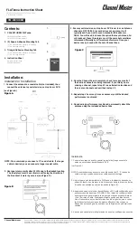
FLATenna
Brand: Channel Master Pages: 2

OMNI-292-V2
Brand: Poynting Pages: 11

GWWPX309SM
Brand: Broadradio Pages: 7

6822
Brand: Shively Labs Pages: 78

OYSTER V PREMIUM
Brand: Ten-Haaft Pages: 52

SW61-R-M9
Brand: SABINE Pages: 12

2380
Brand: A.H. Systems Pages: 14

6-30LP11
Brand: M2 Antenna Systems Pages: 23

HAO9SIP
Brand: Hawking Pages: 2

Stubby 75A
Brand: Tarheel Antennas Pages: 7

Hirschmann BAT-ANT-N-14G-IP23
Brand: Belden Pages: 4

SRB1AC101010
Brand: Safe Fleet Pages: 5

121665
Brand: Hama Pages: 38

XR-520H
Brand: Xirrus Pages: 14

SW3-665 WMMG
Brand: Panorama Antennas Pages: 8

CHA HYBRID MICRO
Brand: Chameleon Antenna Pages: 26


