background image

1

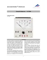
Model DMM135: OPERATING MANUAL

Page

3
4
5
7

10

11

12
13
14
14
15
17
19

 21

23
26

Title

Overview
Unpacking Inspection
Safety Information
Rules For Safe Operation
International Electrical Symbols
The Meter structure
Functional Buttons
LCD Display
Measurement Operation

A.

DC Voltage Measurement

B.

AC Voltage Measurement

C.    DC Current Measurement
D.

 AC Current Measurement

E.

Resistance Measurement

F.

Diode and Continuity Test

Table of Contents (1)

G.    Transistor hFE Measurement

Summary of Contents for DMM135

Page 1: ...on Rules For Safe Operation International Electrical Symbols The Meter structure Functional Buttons LCD Display Measurement Operation A DC Voltage Measurement B AC Voltage Measurement C DC Current Measurement D AC Current Measurement E Resistance Measurement F Diode and Continuity Test Table of Contents 1 G Transistor hFE Measurement ...

Page 2: ...cifications Accuracy Specifications A DC Voltage B AC Voltage C DC Current D AC Current E Resistance F Diodes and Continuity Measurement G Transistor hFE Test Maintenance A General Service B Replacing the Battery C Replacing the Fuses Page 27 28 30 30 31 32 33 34 35 35 36 36 37 38 ...

Page 3: ...y read the Safety Information and Rules for Safety Operation carefully before using the Meter The Model Multimeter hereafter referred as the Meter is a 3 3 4 digits with steady operations fashionable design and highly reliable hand held measuring instrument The Meter can measure AC DC voltage AC DC Current Resistance Transistor hFE Diode and Continuity It is an ideal tool for maintenance Model DMM...

Page 4: ...s carefully to see any missing or damaged part In the event you find any missing or damage please contact your dealer immediately Unpacking Inspection Model DMM135 OPERATING MANUAL Item 1 2 3 Description Qty 1 piece 1 pair 1 piece English Operating Manual Test Lead Holster ...

Page 5: ...double insulation CAT I Signal level special equipment or parts of equipment telecommunication electronic etc with smaller transient overvoltages than overvoltages CAT II CAT II Local level appliance PORTABLE EQUIPMENT etc with smaller transient overvoltages than CAT III Use the Meter only as specified in this operating manual otherwise the protection provided by the Meter may be impaired ...

Page 6: ...tifies conditions and actions that pose hazards to the user or may damage the Meter or the equipment under test A Note identifies the information that user should pay attention on International electrical symbols used on the Meter and in this Operating Manual are explained on page 10 ...

Page 7: ... to the insulation around the connectors l Inspect the test leads for damaged insulation or exposed metal Check the test leads for continuity Replace damaged test leads with identical model number or electrical specifications before using the Meter l Do not apply more than the rated voltage as marked on the Meter between the terminals or between any terminal and grounding l The rotary switch shoul...

Page 8: ...e performance of the Meter may deteriorate after dampened l When using the test leads keep your fingers behind the finger guards l Disconnect circuit power and discharge all high voltage capacitors before testing resistance continuity diodes and current l Before measuring current check the Meter s fuses and turn off power to the circuit before connecting the Meter to the circuit l Replace the batt...

Page 9: ...cident l Soft cloth and mild detergent should be used to clean the surface of the Meter when servicing No abrasive and solvent should be used to prevent the surface of the Meter from corrosion damage and accident l The Meter is suitable for indoor use l Turn the Meter off when it is not in use and take out the battery when not using for a long time l Constantly check the battery as it may leak whe...

Page 10: ...UAL International Electrical Symbols Continuity Test AC Current DC Current Double Insulated Deficiency of Built In Battery Diode Fuse Warning Refer to the Operating Manual Conforms to Standards of European Union Grounding AC or DC ...

Page 11: ...5 OPERATING MANUAL The Meter Structure figure 1 1 LCD Display 2 SELECT Button 3 Rotary Switch 4 COM Input Terminal 5 10A Input Terminal 6 Other Input Terminal 7 Transistor Input Terminal The Meter Structure figure 1 ...

Page 12: ...nctional Buttons SELECT button Selecting for DC and AC current measurement Continuity Test and Diode Test The buzzer sounds when switching from one function to the other Press this button to activate the Meter when it is under Sleep Mode ...

Page 13: ...13 Model DMM135 OPERATING MANUAL LCD Display see figure 2 LCD Display figure 2 ...

Page 14: ...V although readings may be obtained The DC Voltage ranges are 400 0mV 4 000V 40 00V 400 0V and 500V 1 Insert the red test lead into the VWmA terminal and the black test lead into the COM terminal 2 Set the rotary switch to V range 3 Connect the test leads across with the object being measured The measured value shows on the display figure 3 A DC Voltage Measurement see figure 3 black red ...

Page 15: ... or less l When DC voltage measurement has been completed disconnect the connection between the testing leads and the circuit under test B AC Voltage Measurement see figure 3 Warning To avoid harms to you or damages to the Meter from electric shock please do not attempt to measure voltages higher than 500V although readings may be obtained The AC voltage ranges are 4 000V 40 00V 400 0V and 500V 1 ...

Page 16: ...display l DCV Measurement is autoranging the Meter has an input impedance of approx 10MW This loading effect can cause measurement errors in high impedance circuits If the circuit impedance is less than or equal to 10kW the error is negligible 0 1 or less l When DC voltage measurement has been completed disconnect the connection between the testing leads and the circuit under test Note ...

Page 17: ...the Meter may be damaged or the operator himself may be hurt Use proper terminals function and range for the measurement When the testing leads are connected to the current terminals do not parallel them across any circuit Measurement Operation 4 figure 4 To measure current do the following 1 Turn off power to the circuit Discharge all high voltage capacitors black red 17 Model DMM135 OPERATING MA...

Page 18: ...ct the red test lead to the more positive side of the break and the black test lead to the more negative side of the break 5 Turn on power to the circuit The measured value shows on the display Note l If the value of current to be measured is unknown use the maximum measurement position 10A and reduce the range step by step until a satisfactory reading is obtained l When current measurement has be...

Page 19: ...imself may be hurt Use proper terminals function and range for the measurement When the testing leads are connected to the current terminals do not parallel them across any circuit 1 Turn off power to the circuit Discharge all high voltage capacitors 2 Turn the rotary switch to suitable range press SELECT to change from DC to AC measurement 3 Insert the red test lead into the VΩmA or 10A terminal ...

Page 20: ...ING MANUAL 5 Break the current path to be tested Connect the red test lead to the more positive side of the break and the black test lead to the more negative side of the break 6 Turn on power to the circuit The measured value shows on the display ...

Page 21: ...circuit power and discharge all the high voltage capacitors before measuring resistance The Ω ranges are 400 0Ω 4 000kΩ 40 00kΩ 400 0kΩ 4 000MΩ and 40 00MΩ 1 Insert the red test lead into the VΩmA terminal and the black test lead into the COM terminal 2 Set the rotary switch to the Ω range 3 Connect the test leads across with the object being measured The measured value shows on the display ...

Page 22: ...t terminals beforehand and record the reading obtained called this reading as X X Is the additional resistance from the test lead Then use the equation measured resistance value Y X precision readings of resistance l For high resistance measurement 1MΩ it is normal taking several seconds to obtain a stable reading l When resistance measurement has been completed disconnect the connection between t...

Page 23: ...the devices under test disconnect circuit power and discharge all the high voltage capacitors before diodes Use the diode test to check diodes transistors and other semiconductor devices The diode test sends a current through the semiconductor junction and then measures the voltage drop across the junction A good silicon junction drops between 0 5V and 0 8V black red ...

Page 24: ...ce the red test lead on the component s anode and place the black test lead on the component s cathode The measured value shows on the display Note l In a circuit a good diode should still produce a forward voltage drop reading of 0 5V to 0 8V however the reverse voltage drop reading can vary depending on the resistance of other pathways between the probe tips l Connect the test leads to the prope...

Page 25: ...or Continuity To test for continuity connect the Meter as below 1 Insert the red test lead into the VΩ mA terminal and the black test lead into the COM terminal 2 Set the rotary switch to 3 Press SELECT button to select continuity measurement mode 4 Connect the test leads across with the object being measured The buzzer sounds if the resistance of a circuit under test is less than 100Ω ...

Page 26: ...Measurement see figure 7 Warning To avoid damages to the Meter or to the devices under test do not input any current over 60V DC or 30V AC 1 Check that the transistor is PNP or NPN type 2 Connect the transistor to be measured to the corresponding jacks 3 LCD display hFE reference value ...

Page 27: ...To preserve battery life the Meter automatically turns off if you do not turn the rotary switch or press any button for around 15 minutes The Meter can be activated by pressing the SELECT button or turning the rotary switch Sleep Mode ...

Page 28: ...50V fast type φ5x20 mm l 10A Terminal Un fused l Range Auto ranging l Maximum Display Display 3999 l Measurement Speed Updates 3 times second l Temperature Operating 0 o C 40 o C 32 o F 104 o F Storage 10 o C 50 o C 14 o F 122 o F l Relative Humidity 75 0 o C 30 o C 50 31 40 o C l Altitude Operating 2000 m Storage 10000 m General Specifications 1 ...

Page 29: ...f 1 5V AAA Battery l Battery Deficiency Display l Negative reading Display l Overloading Display 0L l Dimensions HxWxL 130 x 73 5 x 35mm l Weight Approx 156g battery included l Safety Compliances IEC61010 CAT I 600V CAT II 300V overvoltage and double insulation standard l Certification ...

Page 30: ... Voltage Remark Input impedance 10MΩ 100µV 1mV 10mV 100mV 1V Accuracy a reading b digits guarantee for 1 year Operating temperature 23 o C 5 o C Relative humidity 75 Range Resolution 400mV 4V 40V 400V 500V Accuracy Overload Protection 0 8 3 0 8 1 500V DC or AC 1 3 ...

Page 31: ...ANUAL Range Resolution 4V 40V 400V 500V Accuracy Overload Protection 1 2 3 500V DC or AC 1mV 10mV 100mV 1V 1 5 5 B AC Voltage Remarks l Input impedance approx 10MΩ l Displays effective value of sine wave mean value response l Frequency response 40Hz 400Hz ...

Page 32: ...us measurement 10 seconds and interval not less than 15 minutes l Input impedance approx 10MΩ l Measurement voltage drop Full range at 400mV Range Resolution 400µA 4000µA 40mA 400mA 4A 10A Accuracy Overload Protection 1 2 500mA 250V fast type fuse φ 5x20mm 0 1µA 1µA 10µA 100µA 1mA 10mA 1 2 2 1 5 5 Un Fused ...

Page 33: ... Accuracy Overload Protection 1 5 5 500mA 250V fast type fuse f 5x20mm 0 1mA 1mA 10mA 100mA 1mA 10mA 2 5 2 5 5 D AC Current Un Fused Remark l At 10A Range For continuous measurement 10 seconds and interval not less than 15 minutes l Input impedance approx 10MW l Measurement voltage drop Full range at 400mV ...

Page 34: ...uracy Specifications 5 34 Model DMM135 OPERATING MANUAL E Resistance Range Resolution 400W 4kW 40kW 400kW 4MW 40MW Accuracy Overload Protection 1 2 2 0 1W 1W 10W 100W 1kW 10kW 1 5 2 1 2 2 1 2 250V DC or AC ...

Page 35: ...Testing Condition 35 Model DMM135 OPERATING MANUAL G Transistor hFE Test Ibo 10mA Vce 1 5V hFE 250V DC or AC F Diodes and Continuity Measurement Displays approximate forward voltage drop reading Buzzer beeps at 100W 1mV 0 1W Can test NPN and PNP type transistor Displays range 0 1000b ...

Page 36: ...lectrical shock or damage to the Meter do not get water inside the case A General Service l Periodically wipe the case with a damp cloth and mild detergent Do not use abrasives or solvents l To clean the terminals with cotton bar with detergent as dirt or moisture in the terminals can affect readings l Turn the Meter to OFF position when it is not in use and take out the battery when not using for...

Page 37: ...injury replace the battery as soon as the battery indicator appears To replace the battery 1 Disconnect the connection between the testing leads and the circuit under test and remove the testing leads away from the input terminals of the Meter 2 Turn the Meter to OFF position 3 Remove the screw from case bottom and separate the case bottom from the case top figure 8 SCREW ...

Page 38: ...fuse 1 Disconnect the connection between the testing leads and the circuit under test and remove the testing leads away from the input terminals of the Meter 2 Turn the Meter to OFF position 3 Remove the screws from case bottom and separate the case bottom from the case top Maintenance 4 4 Remove the battery from the battery compartment 5 Replace the battery with a new 1 5V AAA battery 6 Rejoin th...

Page 39: ...case bottom and case top and reinstall the screw Replacement of the fuses is seldom required Burning of a fuse always results from improper operation 5 Install ONLY replacement fuses with the identical type and specification as follows and make sure the fuse is fixed firmly in the bracket Fuse 1 500mA 250 V fast type f 5x20mm Maintenance 5 ...

Page 40: ...Replacement of the fuses is seldom required Burning of a fuse always results from improper operation END 40 Model DMM135 OPERATING MANUAL ...

Reviews: