TECHCON TS980, User Manual
The TECHCON TS980 User Manual is your essential guide to unlocking the full potential of this innovative product. Ensure optimal usage and seamless operations by downloading the free manual from our website. Discover expert tips, troubleshooting techniques, and detailed instructions to maximize your TS980 experience.
Share
Download


Reviews:
No comments
Related manuals for TS980

AutoJanitor
Brand: Air Delights Pages: 7

Medallist 8"
Brand: Culligan Pages: 58

POU1ACTHSK
Brand: Oasis Pages: 4

12 A RI
Brand: Connect Pages: 24

TCC2S
Brand: Curtis Pages: 21

20210015
Brand: BestWater Pages: 70

IH-99
Brand: U-Line Pages: 15
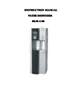
HLM-116B
Brand: Haier Pages: 8
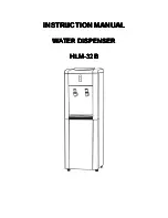
HLM-32B
Brand: Haier Pages: 7

WDNS116BBS
Brand: Haier Pages: 28

WDNS045
Brand: Haier Pages: 44

WDLS056
Brand: Haier Pages: 23

WDNS115BW
Brand: Haier Pages: 44

Pro Fast Gate IDC255
Brand: Cornelius Pages: 2

Enduro/Duraflex Stand 175
Brand: Cornelius Pages: 2

2 Flavor
Brand: Cornelius Pages: 43

VIPER 4 FLAVOR
Brand: Cornelius Pages: 4

15 Gallon Single-Flavor Visual Display Dispenser J15
Brand: Cornelius Pages: 28


