TEC SL-47-N-1 Series, Owner'S Manual
The TEC SL-47-N-1 Series is a top-of-the-line product designed to meet all your technological needs. With its advanced features and sleek design, this product is a must-have for tech enthusiasts. Enhance your user experience by downloading the free Owner's Manual from manualshive.com, providing detailed instructions and essential information.
Share
Download


Reviews:
No comments
Related manuals for SL-47-N-1 Series
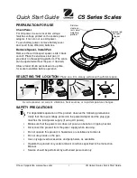
CS Series
Brand: OHAUS Pages: 2

TE10FT
Brand: Taylor Pages: 2

7553
Brand: Taylor Pages: 2

7402
Brand: Taylor Pages: 2

7009
Brand: Taylor Pages: 2

5743
Brand: Taylor Pages: 12

3838
Brand: Taylor Pages: 3

The Biggest Loser 3840BL
Brand: Taylor Pages: 2

SC-212
Brand: Scarlett Pages: 35

WTC 15 C1/L
Brand: RADWAG Pages: 12

H-1096
Brand: U-Line Pages: 15

VDI 15/30
Brand: Vedia Pages: 9

LC114
Brand: Laica Pages: 16

Misura
Brand: Johnson Pages: 16

0775
Brand: eta Pages: 28

Body Manager BWM0002
Brand: Ideal Life Pages: 15

KS 29
Brand: Beurer Pages: 12

BS 477
Brand: Medisana Pages: 28


