background image


of 36 

© 2020 TE Connectivity family of companies 
All Rights Reserved 
| Indicates Change 

*Trademark. TE Connectivity, TE connectivity (logo), and TE (logo) are trademarks.  Other logos, product, and/or company names may be trademarks of their respective owners. 

Application  
Specification 

                                                                  114-94438 REV C1 


18JUN2020 


Class 1 


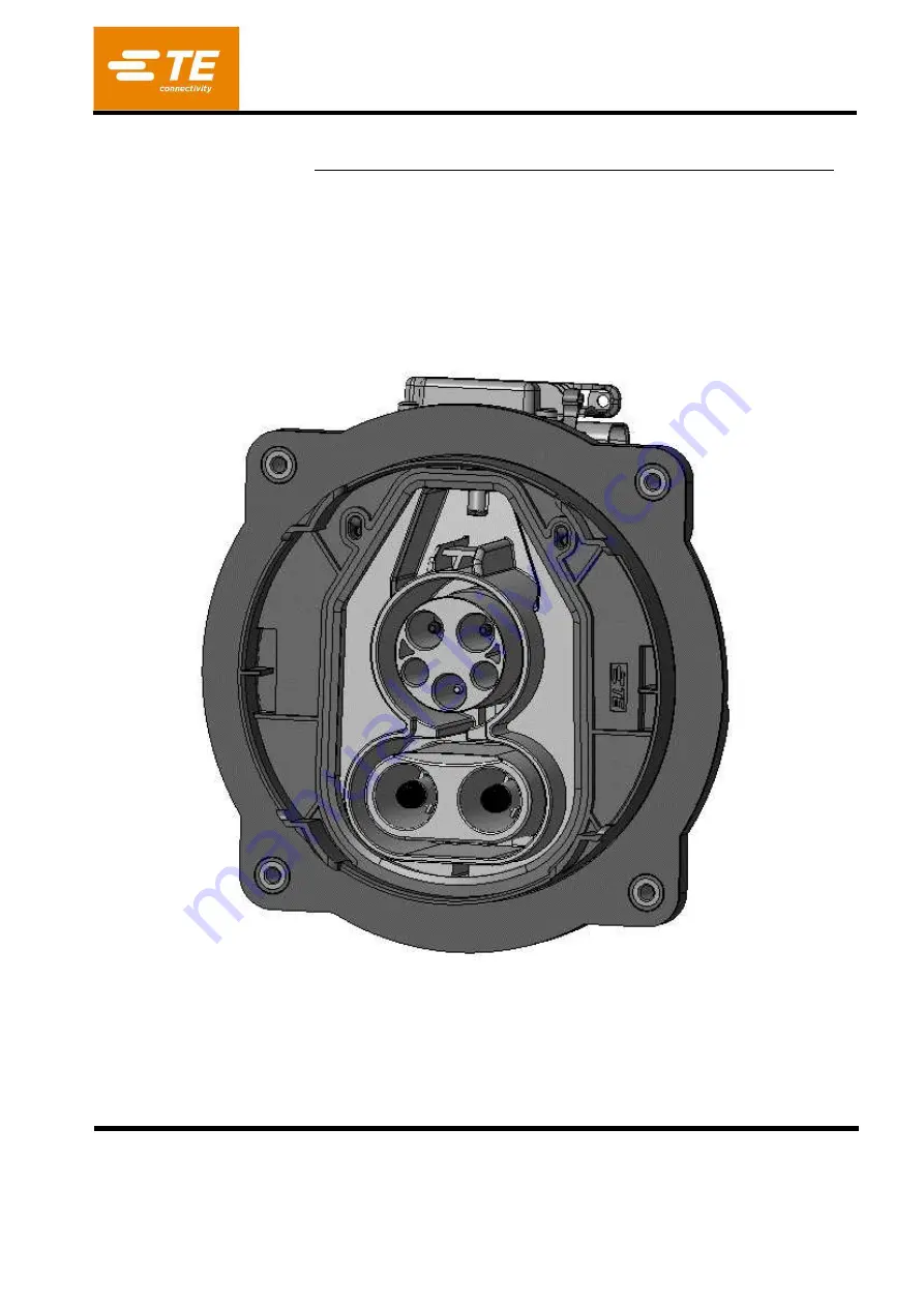
VEHICLE CHARGE INLET CCS1 

acc. IEC62196-3 / SAE J1772 


Summary of Contents for CCS1

Page 1: ...Change Trademark TE Connectivity TE connectivity logo and TE logo are trademarks Other logos product and or company names may be trademarks of their respective owners Application Specification 114 944...

Page 2: ...OLS 6 5 Requirements on the crimped contact 7 5 1 Terms of pin contact 7 5 2 Conductor position 7 5 3 Crimp data for the wire crimp 7 5 4 Crimpposition 8 5 5 Cross sections 10 5 6 Contact area 10 5 7...

Page 3: ...s to manual assembly of the components from series production tooling for the standard version 1 2 Processing Note The processor is responsible for ensuring the quality of the manufacturing process an...

Page 4: ...s specification and the product drawing or this specification and the specified documentation then the product specification has priority 2 1 TE Connectivity Documents a Drawings Bill of material See...

Page 5: ...st be cut accurately and pulled off the conductor Offcut of insulation may not remain on the conductor Single strands may not be damaged fanned out cut or pulled out Furthermore the operator should av...

Page 6: ...ier Contact P N Geometry Applicator Crimping press used by TE for Product Validation Pure copper 6 84 x 0 31mm 13 0 1 3 7 0 1 LV216 2 FHLR2GCB2G 3x6 0mm Coroplast 2293266 3 2 2293266 3 W 7 528041 0 HV...

Page 7: ...ces as well as wire sizes are given in table 1 The crimp height is the key quality feature of a crimp connection The measurement allows a non destroying examination and a continuous process inspection...

Page 8: ...to be monitored Suspect and or worn Die Sets have not to be used for the production of these crimps Die Sets are available as spare parts 5 4 Crimpposition Contacts of diameter 6mm have to be crimped...

Page 9: ...114 94438 REV C1 9 of 36 Contacts of wire diameter 16 mm and 50mm have to be crimped with crimping tool position at end of crimp area as shown Figure 4...

Page 10: ...ontact area During processing and following processing the contact area may not be damaged or bended 5 7 Sealing area During processing and following processing the sealing area may not be damaged or...

Page 11: ...ter 6mm can be performed by inserting it into a suitable housing cavity crimp may not scrape the walls of secondary lock If contacts are bent during the application process exceeding the specification...

Page 12: ...exact appearance of the components can be seen in the drawing documentation 6 1 Assembly overview Charge Inlet CCS I Pos Description Bezeichnung 1 INLET HSG COMBO1 ASSY 2 12P MICRO MNL ASSY 3 PIN DIA...

Page 13: ...s The required configaration can be chosen according to customer requirement Configurations for cable exit AC 90 sidewards Configurations for cable exit AC 20 downwards 6 3 Parts to order See 2 1 a At...

Page 14: ...ION HIGH VOLTAGE APPLICATION CABLE INSULATION MUST NOT BE DAMAGED Figure 12 Figure 13 ESD safety e ui ed The p i ted i uid oa ds a e stati se siti e de i es hi h a e da aged if tou hed ithout the e es...

Page 15: ...LE PROCESS Remove outer isolation shield and filler of AC multicore cable acc figure 15 The given length of the single wires shown in table 3 ensures that the outer isolation of the multicore cable se...

Page 16: ...EAL AC POS 7 Wire Size Removal of isolation A Length to filler B Length to shield braid C Length to outer insulation D Position outer end of COVER POS 9 E 6 mm 13 1 mm 65 2 mm 73 2 mm 78 2 mm 106 4 mm...

Page 17: ...B 16 mm AC 90 rect right left 16 0 1 mm 95 mm REF AC 20 down straight 95 mm REF Table 5 Crimp conductor on PIN DIA 2 8 POWER PE Pos 4 with the specified tools Care shall be taken that all braids are...

Page 18: ...e Variant of CABLE EXIT POS 6 Removal of isolation A Position outer end of COVER POS 9 B 0 35mm AC 90 rect right left Acc 114 13000 80 mm REF AC 20 down straight 75 mm REF Table 6 Push signal terminal...

Page 19: ...ter isolation and shielding braid of DC HV Cable acc dimension B remove inner isolation acc dimension A figure 23 Wire Size Removal of isolation A Removal of shielding dim B Position outer end of COVE...

Page 20: ...C HV wires figure25 Crimp the conductors to the PIN DIA8 0 CONTACT Pos 12 with the specified tools Care shall be taken that all braids are caught in the crimp Not inserted braids may jeopardize HV req...

Page 21: ...figure27 Remove inner isolation acc dimension A figure 27 Wire Size Removal of isolation A Removal of outer insulation B Position outer end of COVER POS 10 C 50mm 23 0 5 mm 29 0 5 mm 50 mm REF Table...

Page 22: ...to be conform to TE Spec 109 18212 The crimp height according table 10 has to be measured according Chapter 5 4 of TE Spec 109 18212 and it has to meet the following requirement Take care of position...

Page 23: ...braids may jeopardize HV requirements Wires shall be completely inserted to be visible through the inspection hole Figure 31 Crimp height H shall be conform to dimension acc table 1 Take care to dista...

Page 24: ...ulation A Removal of outer insulation B Position outer end of COVER POS 10 C 50mm 23 0 5 mm 29 0 5 mm 61 mm REF Table 11 Take care to protect single conductors and braid against contamination bending...

Page 25: ...irements Wires shall be completely inserted to be visible through the inspection hole Figure 36 Crimp height H shall be conform to dimension acc table 1 ATTENTION Any damage of the wire isolation must...

Page 26: ...114 94438 REV C1 26 of 36...

Page 27: ...ted into the Collar of the Cable Exit Cover Ensure also correct orientation of seal acc figure 38 Step 8 Pass the SIGNAL CONNECTOR AC POWER PINS and PE PIN through the AC slot and DC pins through DC s...

Page 28: ...geometry in housing To ensure that the contacts are correctly inserted pull and push with a low force on the cables max 10N and check visually on the front side that the locking lances are properly e...

Page 29: ...by the double audible click and by visible inspection figure 43 ATTENTION The Pin position has to be ensured BEFORE locking the Secondary Lock ESD safety required The printed circuit boards are static...

Page 30: ...aged if touched without the necessary electrostatic discharge ESD precautions During handling of the open inlet assembly ESD safety is required Step 12 Assemble the CABLE EXIT Pos 6 with radial seal P...

Page 31: ...C POS 9 over it and snap it on the CABLE EXIT Pos 6 Ensure that both hooks are properly engaged Typical press on force 250N max press on force 500N Move the FAMILY SEAL DC Pos 11 into the CABLE EXIT P...

Page 32: ...Step 15 Thread the service unlock ball wire through the hole in the actuator housing Snap the ball into the seating of the red unlocking strap as shown in the figure 49 Typical press in force 10N max...

Page 33: ...onnector on actuator housing To ensure that the connector is correctly inserted pull and push with a low force on the housing max 10N Step 17 Apply a label on specified face of CABLE EXIT The label ne...

Page 34: ...1s min Riso 200MOhm AC versus AC AC versus multicore shield DC versus DC DC versus DC shield Dielectric withstand voltage TEST VOLTAGE 1500VAC Inspection duration 1s max leakage current 10mA AC versu...

Page 35: ...ANCE WAS 1 0 TABLE 50MM DIM A WAS 23 5 TABLE 50MM DIM B WAS 30 5 R SCHWAN F WITTROCK 21MAY2019 B TABLE 1 FERRULE 2316553 2 WAS 2316553 1 TABLE 1 APPLICATOR 8 528041 2 WAS 3 528041 8 TABLE 1 10 FERRULE...

Page 36: ...C VERSUS AC AC VERSUS MULTICORE SHIELD DC VERSUS DC DC VERSUS DC SHIELD ADDED 6 6 DIELECTRIC WITHSTAND VOLTAGE TEST VOLTAGE 1500VAC WAS 2000VAC AC VERSUS AC AC VERSUS MULTICORE SHIELD DC VERSUS DC DC...

Reviews: