background image

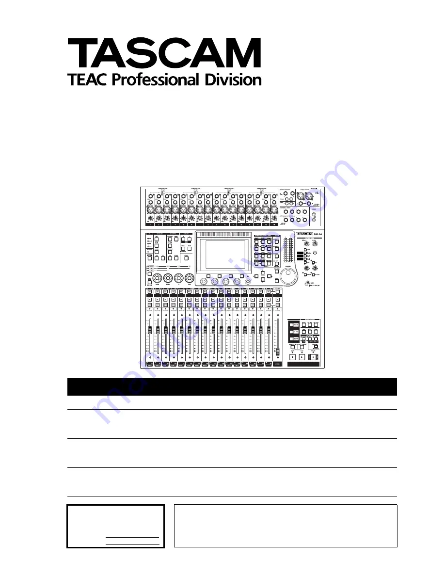
DM-24

Digital Mixing Console

Professional

OWNER’S MANUAL

CAUTION: TO REDUCE THE RISK OF ELECTRIC SHOCK, DO NOT
REMOVE COVER (OR BACK). NO USER-SERVICEABLE PARTS INSIDE.
REFER SERVICING TO QUALIFIED SERVICE PERSONNEL.

The exclamation point within an equilateral triangle is intended to alert the user to the pres-
ence of important operating and maintenance (servicing) instructions in the literature
accompanying the appliance.

The lightning flash with arrowhead symbol, within an equilateral triangle, is intended to alert
the user to the presence of uninsulated “dangerous voltage” within the product’s enclosure
that may be of sufficient magnitude to constitute a risk of electric shock to persons.

This appliance has a serial number
located on the rear panel. Please record
the model number and serial number
and retain them for your records.
Model number
Serial number

Ü

ÿ
Ÿ

WARNING: TO PREVENT FIRE OR SHOCK

HAZARD, DO NOT EXPOSE THIS 

APPLIANCE TO RAIN OR MOISTURE.

9101439701

Summary of Contents for DM-24

Page 1: ...literature accompanying the appliance The lightning flash with arrowhead symbol within an equilateral triangle is intended to alert the user to the presence of uninsulated dangerous voltage within th...

Page 2: ...oved type should be used and be sure to re fit the fuse cover IF IN DOUBT CONSULT A COMPETENT ELECTRICIAN TO THE USER This equipment has been tested and found to comply with the limits for a Class A d...

Page 3: ...g structure grounding of the lead in wire to an antenna discharge unit size of grounding conductors location of antenna discharge unit con nection to grounding electrodes and requirements for the grou...

Page 4: ...de 23 TRA Target link 23 Automation synchronization source 23 TC IN 23 MIDI IN MTC 24 INT 24 INT START TIME 24 FLY WHEEL frames 24 DIGITAL screens 24 CLOCK settings 24 High sampling frequency 25 Fs St...

Page 5: ...and 55 Low band 55 EQ library 55 Aux sends 55 Aux sends global 55 Fader control 56 Setup 56 Copy 56 Source pre post and SOURCE settings 56 Setup 56 Linked aux sends 56 Setup screen 57 Channel source C...

Page 6: ...82 Machine Control mapping memories 82 To use a machine control mapping 83 Viewing the transport mappings 83 Editing a mapping 83 General parameters 83 Program Change channels 83 Program Change value...

Page 7: ...09 Global boom levels 5 1 only 110 15 High sampling frequency To select high sampling frequency 112 Constraints on other devices 112 Channels etc 113 High sampling frequency I O 114 Monitoring 115 Aux...

Page 8: ...nal mixdown expansion with another DM 24 console using an optional cascade slot card both 44 1 kHz and 48 kHz base sampling frequen cies are supported together with dual frequency support 88 2kHz and...

Page 9: ...read the first few sections of this manual They will provide useful background information for you as you use the DM 24 The other sections of this manual are more in the nature of background referenc...

Page 10: ...arried out if the internal system software is to be upgraded 13 Library functions on page 99 Vari ous settings effects EQ settings snapshots and dynamics processors can be stored for later use in inte...

Page 11: ...word clocks from the following sources An external clock connected through the dedicated connector The TDIF 1 interfaces The integral ADAT interface Either of the two DIGITAL IN interfaces Either of...

Page 12: ...e SHIFT indicator is lit The SHIFT key is a smart key Pressing and releas ing it within a short time somewhat less than half a second latches it on and off as shown by the indica tor being lit Pressin...

Page 13: ...screens as shown here the box does not cover the full width of a screen row and the and keys or dial must be used to move the box within the row When a number of on screen controls are highlighted by...

Page 14: ...hes before starting to edit the value with the dial and ENTER once again after editing to confirm the value Using the faders to change values In the global screens there is often a special on screen b...

Page 15: ...1 is used to select the desired option which is high lighted in inverse video Use either the ENTER key or the soft key which was used to pull up the menu to make the selection from the menu Rotary enc...

Page 16: ...to the center is lit as well as the end LED on the appropriate side If the EQ band is set as a high pass for low pass filter or is used as a notch filter depending on the band all LEDs around the rot...

Page 17: ...sent interme diate settings LEDs light to show the current pan position The illustrations below show the pan position at the hard left position and then at a position just right of hard left Encoders...

Page 18: ...acks of external control devices the SEL keys and the MUTE keys When the fader layer is selected the faders move to show the current status of the layer Machine control keys As well as the keys contro...

Page 19: ...o be used The AUTOMATION UNDO key is used in automation operations in order to undo any unwanted changes to automated mixes The operation of the automation facilities is explained in a separate manual...

Page 20: ...ill be shown on the dis play in the timecode position TIMECODE DISPLAY or as a separate popup display in the center of the screen LCD Screen Popup ENCODER OPERATION MODE When using the encoders Rotary...

Page 21: ...the process of calibrating the DM 24 meters WARNING You must turn down the headphone and control room monitor levels before starting this check to avoid any possible damage to your ears and to the con...

Page 22: ...fe of the unit a popup message will automatically appear to alert you of this fact You should then contact your TASCAM dealer for service Version Info For service etc it is useful to know the software...

Page 23: ...he selection of a timecode source for display This displayed timecode may be the source used for auto mation synchronization Sync Source or another source of timecode OTHERS If Sync Source is selected...

Page 24: ...start time FLY WHEEL frames If an external timecode source is selected then it is possible to compensate for loss of incoming signal allowing the DM 24 to flywheel for a set number of frames before i...

Page 25: ...tion frequency here Whether the RCA or XLR connector is used as the clock source is selected in the I O screens Digital inputs on page 39 not here WORD SYNC IN Since the frequency information of any s...

Page 26: ...ce the usual speed where one AES EBU cable is used to transmit a pair of high sampling frequency signals at high speed Use the cursor dial and ENTER key to set this value If the DM 24 is set to an inc...

Page 27: ...On the slot screen the different optional interface cards that can be fitted to the DM 24 are automati cally detected and the options can be set These are described separately in Options on page 118 I...

Page 28: ...is section is not a complete guide to the functions of the DM 24 treat it more as a road map than a guidebook Top surface The top surface of the DM 24 may be conveniently divided into the following se...

Page 29: ...5 through 8 9 through 12 and 13 through 16 Other analog I O These inputs and outputs provide analog feeds to monitoring systems etc a balanced pair of stereo master outputs and an insert loop for the...

Page 30: ...s in parentheses on the first three buss keys refer to surround assignments if a surround mode has been selected I EXT CLOCK indicator If this indicator is lit the DM 24 is referenced to externals wor...

Page 31: ...e than about half a sec ond to light the indicator for only as long as the key is held down when the key is released the indicator goes out When the indicator is lit the predefined function keys will...

Page 32: ...he monitor screen to the monitor outputs f Talkback microphone This integral microphone can be used for studio talkback or slate output g DIM key and indicator This smart key works in the same way as...

Page 33: ...TUS LED TYPE on page 20 for details of these settings q Module faders These 100mm motorized faders are labeled from full cut to 10 dB The 0 position may be set to be equivalent to the appro priate ful...

Page 34: ...ent If the use of cables other than TASCAM cables causes or results in damage the warranty is voided 1 TO METER This 25 pin D sub connector is used to connect the DM 24 and the optional MU 24 DM meter...

Page 35: ...ol the recorders 9 SLOT 1 and 2 These expansion slots allow the fitting of optional cards such as a cascade card AES EBU interfaces additional lightpipe inter faces or additional AD DA conversion inte...

Page 36: ...rough 24 The ADAT connector audio is selected as the return source lower box for these channels Sixteen mic line analog inputs are avail able on the DM 24 These are referred to on screen as M L They m...

Page 37: ...gnable sends These sends may be used as either analog insert sends or as aux sends Digital outputs x 2 Can be assigned to output the stereo buss adjacent pairs of busses adjacent pairs aux busses or t...

Page 38: ...creen below however tape returns from TDIF groups 1 and 2 are assigned to these channels for mixdown Channels 25 through 32 can be used for input only Input sources Any mic line input can be assigned...

Page 39: ...cannot be changed For example if an MTR return is assigned to channels 1 8 track 2 of an MTR cannot be assigned to channel 1 Track 3 can only be assigned to TDIF channel 3 in the TDIF1 TDIF2 TDIF3 re...

Page 40: ...4 5 6 and 7 8 the stereo output ST direct out DIR or AUX 1 2 see below 5 Press ENTER to assign de assign the high lighted channel to and from the selected group The appropriate CH ASSIGN key indi cat...

Page 41: ...ULE or the ASSIGN screen is dis played changes made to the assignments using these keys will be reflected in the display Other module parameters Phase gate on off compressor on off pre or post EQ comp...

Page 42: ...or the block channel combination used by the direct outs The composition of the output blocks and the choices for the block sources are In the I O OUTPUT sub screen use the dial and ENTER key to selec...

Page 43: ...n or off ON OFF button in the ON OFF column If the send loop is selected the SEND RETURN radio button is selected the send signal source AUX 1 to AUX 6 can be selected To select the send signal source...

Page 44: ...analog inputs are the mic line source con nections made to the MIC LINE connectors at the top of the unit Both sets of connectors are balanced though when unbalanced plugs are inserted into the LINE 1...

Page 45: ...se inserts is fixed as post trim and immediately before the AD convertor The assignable sends and returns can be set up as insert loops or as send return effect loops Assign able sends and returns on...

Page 46: ...TDIF interface of the DTRS unit using a TASCAM cable The interface carries both input and output signals Use an appropriate TASCAM remote cable to con nect the DTRS REMOTE CONTROL connector of the DM...

Page 47: ...ese inputs can be assigned to any of the channel modules 1 through 32 They can therefore be used as returns from digital effects units etc as well as source inputs from CD players DAT decks etc The DM...

Page 48: ...in the right position 75 ohm IN termination is ON All input and output is at TTL level Select the word sync source using the CLOCK screen in the DIGITAL section CLOCK settings on page 24 NOTE It is n...

Page 49: ...air pressing the SEL key of either module of the pair will bring up the screen allowing control of both modules see the section on Linked modules on page 60 for further details It is possible to rever...

Page 50: ...button allows the com pressor to be turned on and off ENTER key with a dynamics graph The gain reduction meter also applies to the compressor The appearance of this button changes depending on what l...

Page 51: ...t and is solid if the EQ is enabled NOTE It is not possible to change the buss assignments or the EQ switching from here Use the dedicated keys to the left of the display screen for this Full details...

Page 52: ...rol fully clockwise shows REVERSE on the screen NOTE In the Options screen Balance Level CENTER 0dB on page 21 the way in which the balance control level is modified at the center position can be chan...

Page 53: ...ough the list of stored settings 5 Use the fourth soft key RECALL to recall the highlighted setting Only gates or expanders can be recalled to the GATE section and compressors to the COMP section The...

Page 54: ...the EQ cannot be heard The EQ parameters are as following On off all bands Each band can be turned on or off individually using the on screen button beside the gain control ENTER key If a band is turn...

Page 55: ...and third rows of the screen is used to control the pan position of the signal sent to the stereo aux send In addition as explained in the section on the user interface Encoders used as aux send contr...

Page 56: ...to mirror the stereo output for example which can then be adjusted as necessary Move the cursor to the bottom right of the screen and use POD 1 to select the CH FADER LVL AUXx LVL or the other way rou...

Page 57: ...t the bottom left allowing all pan and balance settings or a selected set to be made identical as well as a bidirectional copy facil ity allowing channel to aux as well as aux to chan nel pan setting...

Page 58: ...through 32 only the pre and post options are available here NOTE Note that even if aux sends1 and 2 are unlinked the settings of both are modified together using this con trol Compression insert COMP...

Page 59: ...Setup A master trim can be applied to selected channels by moving the cursor to the bottom left position setting the desired value with POD 1 and pressing ENTER The scope of the setting is determined...

Page 60: ...modules have been linked pressing the SEL key of one module of the pair selects the pair The parameters and settings which are shared by the pair are Channels Digital Trim Gate only Ch1 16 Com pressor...

Page 61: ...ls are linked or unlinked Recheck the grouping patterns after making or breaking these stereo links Screens for linked modules The screens controlling stereo linked modules differ from unlinked module...

Page 62: ...two boxes select either the AUX CH or the CH AUX setting radio but ton Naturally it is not possible to select both in the same box though it is possible to select CH AUX in one box and AUX CH in the...

Page 63: ...16 also allow the independent turning on and off of the gate expander In the DYNAMICS screen channels 1 through 16 the gate or expander can be turned on and off and the compressor can also be turned o...

Page 64: ...NK L R This allows triggering of two compres sors by a common trigger signal NOTE The linking of the compressors cannot be turned off when two channels have been linked The above screen display shows...

Page 65: ...efore unavailable This includes the soft keys only the compressor library is available from these screens Insert point The insert point is fixed to pre fader Linking The way in which the links are lab...

Page 66: ...st row Variable from 0ms to 990ms in 100 steps Gate decay time DECAY controlled by the POD 3 knob on the last row Variable from 50ms to 5 0s From 5ms to 200ms the steps are 5ms apart from 200ms to 300...

Page 67: ...sed if the compression settings have resulted in gain reduction Output gain OUTGAIN controlled by the POD 4 knob on the last row grayed out if the auto make up above is on Variable from 20dB to 20dB i...

Page 68: ...omp 3 Overall compressor setting 015 Post Pro 1 Useful in post production environments 016 Post Pro 2 Useful in post production environments 017 Narration For the spoken word Program Number Name Comme...

Page 69: ...h a way that press ing the MUTE key of the master channel of a mute group affects the mute status of all the other slave channels in the group Slave mute may be turn on or off independently of the oth...

Page 70: ...rouped together in such a way that mov ing the master fader of a group affects the fader level of all the other slave faders in the group Slave faders may be moved independently of the other faders in...

Page 71: ...oup settings Grouping layers It is often useful to make groups of groups in order to simplify mixing This applies to both fader groups and to mute groups For example when using mute groups you might f...

Page 72: ...ing to make a circular group layer for example making group 5 into a submaster of group 2 and then attempting to make group 2 a submaster of group 5 brings up an appropriate error message Cannot assig...

Page 73: ...nal sent from the analog outputs is adjusted by the CR control The level of the signal sent from the headphone jacks both headphone jacks together is adjusted using the PHONES control Control room sig...

Page 74: ...ot be changed If the control room output is set to one of the DIGITAL OUTPUTS 1 or 2 as explained earlier Control room outputs on page 73 it is not pos sible to monitor the 2 track source In addition...

Page 75: ...ws one channel the one whose MUTE key was pressed last to be soloed at one time SOLO LINK This option allows the fader and mute groups see Grouping on page 69 to be used with the solo function If one...

Page 76: ...group master all channels which belong to that group will be soloed More than one group may be soloed at a time in Mix Solo mode If Exclusive Solo is selected as the solo mode the channel whose MUTE...

Page 77: ...illa tor frequency to be selected 100Hz 440Hz 1kHz or 10kHz The level of the oscillator is also variable POD 2 from 36 0dBFS to 0 0dBFS in 0 5dB steps Use soft key 1 to turn the oscillator on button i...

Page 78: ...key 2 will still be lit that is channel 18 When the Meter Follows SEL key option is checked the meter layer automatically changes when an appropri ate SEL key is pressed The modes are as follows NOTE...

Page 79: ...s can also be used to navigate around the groups Meter and fader setup Use this screen to set meter characteristics and to transfer a specific value to a fader or group of faders Fader level Use POD 1...

Page 80: ...cursor to the ADD button and press ENTER The device will be added to the list To obtain more information regarding a particular item in the list of devices which may be controlled by the DM 24 highlig...

Page 81: ...wer has been applied it may take between one and two minutes for the remote devices to be rec ognized Even if they have been added to the memo rized Machine Control list previously it may not be possi...

Page 82: ...e new assignment or the cursor keys to dismiss this message and return to the previous assignment NOTE When the MASTER indicator is lit the master layer is selected the module REC keys have no effect...

Page 83: ...g a mapping When a mapping has been made parameters other than the transport control may be edited for instance the use of the REC keys To make these changes a permanent part of the cur rently loaded...

Page 84: ...Active Sensing This turns the Active Sensing output from the DM 24 on and off OUTPUT MTC when slaved This controls whether the DM 24 will output MTC as an echo of the input timecode when it is acting...

Page 85: ...f cueing mode is not selected when a fast transport key is pressed irrespective of the current transport mode the unit enters the fast transport mode even when the fast transport key is released Locat...

Page 86: ...on memory which will store the value The EDIT indicator lights steadily 3 Enter the timecode value using the numeric keypad The display shows the value filling up from the right digit towards the left...

Page 87: ...the distance between the two points is very short the behavior of the repeat playback depends on the device being controlled Auto punch operations For DTRS units the three AUTO PUNCH keys RHSL IN OUT...

Page 88: ...of controllers see MIDI controllers on page 93 and the Control Change number in the case of faders see MIDI faders on page 93 To delete a device from the active list move the cur sor to the left part...

Page 89: ...ilable in the eight track mode Consult your DA 98HR documen tation for full details of some of these features DIGITAL INPUT Use this to change between the TDIF and AES EBU inputs INPUT PATCH The input...

Page 90: ...cursor keys dial and ENTER key to change these assignments For DA 78HR units these can be selected as Track T Digital A or Analog A and for DA 98HR units they can be Track T Digital D or Slot S The o...

Page 91: ...to two units can be con trolled using another screen in the same way as for the DA 98HR In this case the DTRS Mixer device must be added to the list of controllable devices If this item is not added t...

Page 92: ...machine offset value The clock sources are restricted to internal and word DA 88 This provides the following facilities as shown on the screen here Similar to the DA 38 digital input can be switched o...

Page 93: ...IDI faders In the MIDI faders screen the master layer of the DM 24 faders is used to control MIDI Control Change values on the same controller for all sixteen MIDI channels The MIDI Control Change num...

Page 94: ...Sound Controller 6 16 GP Controller 1 76 Sound Controller 7 17 GP Controller 2 77 Sound Controller 8 18 GP Controller 3 78 Sound Controller 9 19 GP Controller 4 79 Sound Controller 10 20 31 Undefined...

Page 95: ...T of the remote unit Enter the MIDI BULK SEND RECEIVE screen by pressing MIDI MC key with the SHIFT indicator lit Then use soft key 3 to bring up this screen It is possible to save the library memorie...

Page 96: ...the DM 24 As the DM 24 resets itself after the software has been updated this may cause unwanted thumps etc in the audio chain 2 Connect the MIDI IN of the DM 24 to the OUT of the remote device 3 On t...

Page 97: ...dial and ENTER key NOTE The following Control Changes are not available for use with this function 0 6 32 38 and 96 through 127 If two channels have been linked the even numbered channel of the pair...

Page 98: ...2 4 5 7 8 10 13 16 19 64 67 84 99 101 O O O O b 0 3 6 9 14 15 20 63 65 66 68 83 85 98 100 102 119 x x x x x x 0 119 O O c Prog Change True O 1 127 O 1 127 Assignable 1 b b Snapshot Effect1 Effect2 c B...

Page 99: ...ith the settings in these locations being set up containing useful pre set values The effect libraries are divided into two types preset P where none of the locations can be overwritten and a user lib...

Page 100: ...wn an appropriate error message is displayed and the data is not stored If data already exists in the library entry a popup message appears to show that data is already there and will be overwritten 5...

Page 101: ...to be edited use the dial to pick the NAME special command and press ENTER This copies the entry name to the name editing area Use the cursor keys to navigate the cursor around the name editing area o...

Page 102: ...f the setup to prevent the recalled snapshot from overwriting them This means that only the important parts of a snapshot can be used for example the I O and buss assignments can be retained and not o...

Page 103: ...2 Press the ENTER key to select the sub library Use the normal procedures to store recall and name the effector entries Preset entries can be recalled and then edited and stored in the user sub libra...

Page 104: ...rary or the other way round However expanders and gates may be mixed in the expander gate library The type of dynamics processor which is stored is shown to the right of the title in the list This can...

Page 105: ...ether the EQ band has been configured as a shelving peaking notch or LPF or HPF filter Storing editing and naming and recall operations are all as described in Managing library entries on page 99 005...

Page 106: ...od Bass Upright plucked double bass 05 Synth Bass 1 For synth bass sounds 06 Synth Bass 2 07 Acoustic Guitar Suitable for acoustic guitars 08 Ele Guitar 1 For electric guitars 09 Ele Guitar 2 10 Ele G...

Page 107: ...n firm the new setting or cancel it A plan view of the speaker layout is shown on the display screen Note that in the 5 1 screen the two rear speakers can be selected as a single mono output Monitorin...

Page 108: ...nother piece of equipment in the system Assigning modules When a surround mode has been selected the ASSIGN BUSS screen changes so that the usual buss assign ments are not shown but the modules are no...

Page 109: ...ct the chan nel and POD 4 to select the output channel and make and un make assignments to the channels using the ENTER key Soft keys 1 and 2 are used for on screen buttons allowing all channels to be...

Page 110: ...rce near the cen ter through 50 and 75 to 100 the whole of the sound stage is available Using these parameters it is therefore possible to set the position of a signal precisely or loosely in either d...

Page 111: ...the cursor to the on screen SET button and press ENTER After making a global setting in this way use the cursor keys and PODs to trim the individual channel levels as desired It is also possible to us...

Page 112: ...If other devices are not connected properly this may cause noise in the monitoring system when the DM 24 restarts Make sure that all monitoring equipment lev els are turned down or the monitoring equi...

Page 113: ...e MODE choice at the top of the screen highlighted here is either NORMAL DUAL LINE or HIGH SPEED NOTE These settings can also be made in normal sampling fre quency mode but the frequency conversion mu...

Page 114: ...of the TDIF con nectors are reduced to four in this mode The output screen changes as shown here as only four output channels are available on each output groups The eight output busses are therefore...

Page 115: ...nly four aux sends the aux send screens change For instance the module Aux screen is slightly stripped down to show only four Aux sends When the AUX 5 6 key is pressed and the DM 24 is in high samplin...

Page 116: ...hannels rather than 32 Also note that the range for delay times remains the same even though the sampling frequency is different Libraries Because of the different configuration of the DM 24 in normal...

Page 117: ...s or provides facilities for 32 channels in high frequency mode this will be halved to 16 For example in this screen the meter layer cannot follow channels 17 through 32 they do not exist and therefor...

Page 118: ...e anti static protective bag 4 Hold the card by the edges and insert it component side upwards into the slot 5 Locate the card into the connector inside the DM 24 Push the card firmly without forc ing...

Page 119: ...bit 96 kHz 5 1 automated mixing environment Setting up the cascade When the connection between the two cascade cards has been made turn on the slave unit followed by the master unit Wait until the fad...

Page 120: ...r also names and stores it on the slave and recalling this snapshot on the master also recalls it on the slave This data must be dumped and reloaded individually from each unit for further use Automat...

Page 121: ...the MULTI I O section of The FORMAT screen on page 26 The output parameters cannot be changed fixed at 24 bit with the emphasis status echoing that of the input ADAT card The optional ADAT card provi...

Page 122: ...AES audio standards However some units output audio data which is actu ally correct but one or two bits in the audio cause it to be interpreted as invalid If you are using one of these units as an in...

Page 123: ...e eight output tracks associated with this card can be selected 1 8 9 16 17 24 Remember that if this card is selected for output from the eight busses it can be used to drive a surround multi speaker...

Page 124: ...t impedance 5k ASSIGNABLE SENDS 1 through 4 Quasi balanced 1 4 jacks Nominal output level 2dBu Maximum output level 14dBu Output impedance 100 2 TR IN L R 2 x RCA pin jacks Nominal input level 10dBV H...

Page 125: ...specifications 24 bit word length Sampling frequencies Internal 44 1kHz 48kHz 88 2kHz 96kHz high sampling frequencies External 6 0 WORD SYNC IN BNC connector Switchable 75 termination TTL level WORD...

Page 126: ...0 5dB 1 5dB MIC LINE IN to INSERT SEND 0 5dB 1 0dB LINE IN to STEREO OUTPUT 0 5dB 1 0dB LINE IN to BUSS AUX OUTPUT 0 5dB 1 5dB 2TR IN to MONITOR OUTPUTS 20Hz 25kHz 20Hz 20kHz 20Hz 20kHz 20Hz 25kHz No...

Page 127: ...Explanation Flash Write Count EQ Library aaaa Gate Expand Library bbbb Comp Library ccccc Effect Library dddddd Snapshot Area 1 eeee Area 2 fffff Area 3 gggg Area 4 Press ENTER to continue The messag...

Page 128: ...the normal transmission in high sampling frequency mode must be dual line or high speed High sampling fre quency on page 112 Can t select Normal Different Fs mode Press ENTER to continue An attempt is...

Page 129: ...s been made to load gate expander settings from the library to a module where a gate or expander has not been inserted Library functions on page 99 Can t select dual line Different Fs mode Press ENTER...

Page 130: ...compressor library entry xxx has been successfully recalled and the set tings applied to channel y Library functions on page 99 COMP Libraryxxx is Read Only An attempt is being made to overwrite a re...

Page 131: ...e flash memory specified here has been used the number of times specified Although you can continue to use the unit safely for some time to come we rec ommend that you consult your TASCAM service cent...

Page 132: ...ursor key to cancel Shown when Bulk data is being transferred to the DM 24 Bulk transfer of data to the DM 24 on page 96 The type of data is shown on the second line MIDI Bulk Load Ready _ Press a cur...

Page 133: ...l mapping memories on page 82 OK to assign STEREO to Aux1 2 Press ENTER to confirm or a cursor key to cancel Shown when assigning a link of stereo to Aux 1 2 to overwrite a setting of Aux 1 2 to Stere...

Page 134: ...al input data CLOCK settings on page 24 Signal Info Digital in1 Format AES EBU Contents Audio Emphasis None Channel Mode Two channel Fs 44 1kHz Word Length 24bit Press ENTER to continue Sample popup i...

Page 135: ...s 44 1kHz Word Length 24bit Press ENTER to continue Sample popup information for optional AES slot card output CLOCK settings on page 24 Signal Info Slot1 Option AES3 Card Press ENTER to continue Samp...

Page 136: ...will cause a current group assignment to change Linking and unlinking modules on page 60 ST LINK OFF CH ODD EVEN Press ENTER to confirm or a cursor key to cancel Shown when SEL keys are used to break...

Page 137: ...ancel Shown when the stored sampling frequency does not match the current sam pling frequency automation data recall Unmatched timecode Do not show this message in the future Press ENTER to confirm or...

Page 138: ...IN 2 2TR BUSS1 8 C ROOM SEL DIR DIR POST to METER OSC TONE TO SLATE TO STUDIO MONO D IN 1 L D IN 1 R D IN 2 L D IN 2 R AUX 5 AUX 6 FX 1 L FX 1 R FX 2 R FX 2 L BUSS 1 8 DIR1 8 BUSS 1 8 DIR9 16 MIC LIN...

Page 139: ...POST to METER OSC TONE MONO D IN 1 L D IN 1 R AUX 3 FX 1 L FX 1 R BUSS 1 4 DIR1 4 BUSS 5 8 DIR5 8 MIC LINE INST 48V A D Analog INPUT 1 8 56dBu to 2dBu 42dBu to 12dBu 2dBu TRIM Assignable RTN A D 2dBu...

Page 140: ...20 0 dBFS 16dBFS DAC dBV dBu 2 7dBu 13 3dBu 2dBu 1 4 Assinable SEND 20 10 0 10 20 20 10 0 10 20 0 dBFS 16dBFS DAC dBV dBu 2 7dBu 13 3dBu 4dBu C ROOM OUTPUT EQ 18dB 18dB 10dB INPUT FADER STEREO FADER...

Page 141: ...control keys and indicators 34 data 95 99 fader OFF 22 keys 18 memory 22 23 AUTOMATION UNDO key 31 aux 1 and 2 source AUX 1 2 SOURCE 58 aux sends 15 17 55 115 in snapshot 00 102 aux sends global 55 B...

Page 142: ...controls 17 as EQ frequency controls 16 as EQ gain controls 16 as pan controls 17 as Q controls 16 function select key and indicators 30 operation mode 20 ENTER key 32 entering numbers 31 EQ 54 buss...

Page 143: ...linked channels 21 61 linked dynamics processors 64 linked modules 60 linking and unlinking modules 60 locate display mode 20 locate keys and indicators 31 locate preroll 85 location manual 87 manual...

Page 144: ...nd indicators 33 R repeat play machine control 87 return modules 39 return source 24 39 58 122 rotary encoders ring LEDs 15 30 RS 422 35 timecode 23 S sampling frequency 25 26 sampling frequency conve...

Page 145: ...82 TRA Target link 23 track arming 82 transport and automation control 33 transport keys and indicators 33 trim and delay 116 turning dyaanmics processors on and off 63 turning groups on and off 70 7...

Page 146: ...s Park Watford Hertfordshire WD1 8TE U K TEAC DEUTSCHLAND GmbH Phone 0611 71580 Bahnstrasse 12 65205 Wiesbaden Erbenheim Germany TEAC FRANCE S A Phone 01 42 37 01 02 17 Rue Alexis de Tocqueville CE 00...

Reviews: