background image

WIRELESS DIGITAL POOL THERMOMETER

1. Description Of Parts
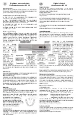
Fig. 1 Receiver

A1: Main unit temperature

A2: Main unit low power symbol

A3: Water temperature

A4: RF symbol

A5: Channel number

A6: Buttons

A7: Water maximum and minimum symbol

A8: Water low power symbol

A9: Main unit maximum and minimum

A10: Wall mounting hole

A11: Battery cover

A12: Support

Fig. 2 Transmitter

B1: LCD screen

B2: Screw cover

B3: Body

B4: Rope

2. Before You Start Using It

• Please make sure to read the instruction manual carefully. This 

information will help you to familiarise yourself with your new de-

vice, to learn all of its functions and parts, to find out important de-

tails about its first use and how to operate it and to get advice in 

the event of a malfunction.

• Please take particular note of the safety advice.

• Please keep this instruction manual for future reference.

3. Scope Of Delivery

• Wireless thermometer (Receiver)

• Water transmitter (CH1)

• Instruction manual

4. Specifications

• Measuring range main unit: Temperature -10°C ~ +60°C (14°F 

~ 140°F).

• Measuring range of water thermometer: Temperature -20°C ~ 

+60°C (-4°F ~ 140°F).

• Accuracy: Tempe/-1°C(2°F) between 0°C to 50°C, oth-

/-2°C(4°F).

• Batteries: Receiver 2 x 1,5V AAA (not included), water transmitter 

2 x 1,5V AAA (not included).

• Transmission distance: 60m in free field.

• Transmission frequency:433MHZ.

• Transmission time: CH1:50s.

• Low battery index.

• Maximum and minimum temperature display.

• Water transmitter IP level:7.

5. For Your Safety

• This product is exclusively intended for the field of application 

described above. It should only be used as described within these 

instructions.

•Unauthorized repairs, modifications or changes to the product are 

prohibited.

Caution! Risk of injury:

• Keep these instruments and the batteries out of the reach of chil-

dren.

• Batteries must not be thrown into a fire, short-circuited, taken 

apart or recharged. Risk of explosion!

• Batteries contain harmful acids. Low batteries should be changed 

as soon as possible to prevent damage caused by leaking.

• Never use a combination of old and new batteries together, nor 

batteries of different types.

6. Getting Started

6.1 Inserting the batteries in the receiver

• Place both instruments on a desk with a distance of approximate-

ly 1.5 meter. Avoid getting close to possible interference sources 

(Electronic devices and radio installations).

• Remove the protective foil from the display of the receiver.

• Remove the battery cover and insert two new alkaline batter-

ies 1,5V AAA, polarity as illustrated, close the battery compartment 

again.

• LCD segments will be displayed for a short moment.

• Display main unit temperature.

• The symbol   blinking and to search the signal from transmitter.

6.2 Inserting the batteries in the pool transmitter

• Open the screw cover of water transmitter as fig. 3.

• Insert two new alkaline batteries 1,5V AAA, polarity as illustrat-

ed (fig. 4).

ko0720

   320281

Info/ Tootja/ Ražotājs/ Gamintojas/ Изготовитель:

Tarmo Finland, PO Box 499, FI-33101 Tampere, Finland/ Тампере, Финляндия

320281_vesilämpömittari_ko_EN_FI-SV-ET-LV-LT-RU.indd   1

320281_vesilämpömittari_ko_EN_FI-SV-ET-LV-LT-RU.indd   1

12.8.2020   8.20.33

12.8.2020   8.20.33

Summary of Contents for 320281

Page 1: ...afety This product is exclusively intended for the field of application described above It should only be used as described within these instructions Unauthorized repairs modifications or changes to t...

Page 2: ...itter and as semble it then the water transmitter will transmit signal to receiv er and the red led flashing the receiver receive the signal and dis play the value on the display Open Screw cover Tran...

Page 3: ...splay After the third channel press the CH button again The cycle display symbol will be displayed Press the CH button again to deactivate the alternating channel and the first water transmitter will...

Page 4: ...5 Turvallisuusohjeet T m tuote on tarkoitettu ainoastaan yll kuvattuun k ytt n Sit saa k ytt vain n iden ohjeiden mukaisesti Laitteen luvaton korjaaminen muuttaminen tai muokkaaminen on kielletty Var...

Page 5: ...een l hetin l hett signaalin vastaanot timeen ja punainen LED valo alkaa vilkkua merkiksi siit ett vas taanotin on vastaanottanut signaalin N yt ss n kyy arvo Avaa Ruuvattava kansi L pin kyv kansi sil...

Page 6: ...ill 1 3 Voit my s valita kanavat n ytett v ksi n ytt n vuorotellen Pai na CH painiketta uudelleen kolmannen kanavan j lkeen jolloin n yt ss n kyy merkki Paina CH painiketta uudelleen poistaaksesi vaih...

Page 7: ...niv 7 5 F r din s kerhet Denna produkt r endast avsedd f r s dan anv ndning som be skrivs ovan Den ska endast anv ndas i enlighet med dessa an visningar Oauktoriserade reparationer eller ndringar av...

Page 8: ...Vattens ndaren skickar d en signal till mot tagaren och den r da LED indikatorn blinkar Mottagaren tar emot signalen och visar v rdet p sk rmen ppna H lje med skruvar Genomskinligt h lje t tningsring...

Page 9: ...xla mellan kanalerna 1 till 3 Du kan ocks v lja att kanalerna ska visas v xelvis Efter den tredje kanalen tryck p CH knappen igen s visas symbolen Tryck p CH knappen igen f r att inaktivera v xlingen...

Page 10: ...n idik Veesisese saatja IP tase 7 5 Teie ohutus See seade on m eldud kasutamiseks ainult lal kirjeldatud ots tarbel Seda tohib kasutada ainult nende juhiste j rgi Toote omavoliline parandamine kohanda...

Page 11: ...pange see kokku Seej rel saadab saatja signaali vastuv tjasse ning vilgub punane LED tuli Kui saatja signaal j uab vastuv tjasse kuvatakse n idikul m tmistulemust Avage Kruvikate L bipaistev kate Sili...

Page 12: ...ast kol mandat kanalit vajutage uuesti nuppu CH Kuvatakse ts kli s m bol Vajutage uuesti nuppu CH et l litada v lja kanalite vaheldumi si kuvamine ning kuvada pidevalt esimese veesisese saatja m t mis...

Page 13: ...im l s temperat ras r d jums dens raid t ja IP l menis 7 5 Dro bas ieteikumi is izstr d jums ir paredz ts tikai iepriek aprakst tajai lietojuma jomai To dr kst izmantot tikai saska ar ajos nor d jumos...

Page 14: ...uztv r js sa ems sign lu un v rt ba tiks att lota displej Ja dens v rt bas neizdodas sa emt 3 min u laik displej pa Atv r ana Skr v jamais p rsegs Caursp d gais p rsegs Silikona bl vgredzens LCD druk...

Page 15: ...t ar izv l ties main gu kan lu att lojumu P c tre ka n la v lreiz nospiediet pogu CH tiks par d ts cikla att lojuma simbols V lreiz nospiediet pogu CH lai deaktiviz tu main go kan lu pir mais dens rai...

Page 16: ...emos baterijos krovos indikatorius Maksimalios ir minimalios temperat ros rodymas Povandeninis si stuvas IP klas 7 5 Saugos rekomendacijos is prietaisas naudotinas tik pagal nurodyt paskirt Jis turi...

Page 17: ...audonas LED indikatorius Kai imtuv pasiekia si stuvo signalas ekrane pasirodo atitinkamas matavimo rezultatas Atidaryti Var tu prisukamas dangtelis Skaidrus dangtelis Silikoninis sandarinimo iedas LCD...

Page 18: ...r pasirinkite i trij kanal Taip pat galite nustatyti kad kanalai ekrane b t rodomi pakaito mis Po tre iojo kanalo dar kart paspauskite CH mygtuk Pasiro dys ciklinio rodinio simbolis Paspauskite CH myg...

Page 19: ...C 2 C 4 F 2 x 1 5 AAA 2 x 1 5 AAA 60 433 CH1 50 IP 7 5 6 6 1 1 5 1 5 6 2 3 1 5 4 ko0720 320281 Info Tootja Ra ot js Gamintojas Tarmo Finland PO Box 499 FI 33101 Tampere Finland 320281_vesil mp mittari...

Page 20: ...3 4 5 5 6 3 3 CH1 3 3 6 C F 320281_vesil mp mittari_ko_EN_FI SV ET LV LT RU indd 20 320281_vesil mp mittari_ko_EN_FI SV ET LV LT RU indd 20 12 8 2020 8 20 41 12 8 2020 8 20 41...

Page 21: ...X MIN CLEAR 7 2 C F C F 8 CH1 2 3 6 CH CH 1 3 CH CH 9 60 10 10 1 11 1 2 3 12 WEEE Tarmo 320281 2014 53 EU tammerbrands eu id 320281 320281_vesil mp mittari_ko_EN_FI SV ET LV LT RU indd 21 320281_vesil...

Reviews: