background image


Read this instruction manual carefully, 
before you install and operate the pump. 

2014 rev. 1 
 
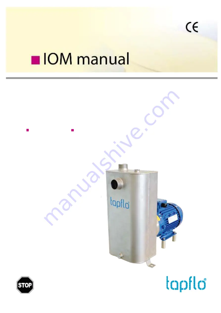
Instructions for installation, start up, operation and maintenance.  
Self-priming CTS H pumps in electro polished AISI 316L stainless steel. 
Self-priming CTS I pumps in glass blasted AISI 316L stainless steel. 

 
Pump models: 


CTS I 


CTS H 


With 2900 rpm motor:


With 2900 rpm motor:


CTS I CC-22  


CTS H CC-22  


CTS I CE-22  


CTS H CE-22  


CTS I DD-40  


CTS H DD-40  


CTS I DF-40  


CTS H DF-40  


CTS I EF-55  


CTS H EF-55  


CTS I EG-55  


CTS H EG-55  


CTS I EF-75  


CTS H EF-75  


CTS I EG-75 


CTS H EG-75 


Summary of Contents for CTS I

Page 1: ...pumps in electro polished AISI 316L stainless steel Self priming CTS I pumps in glass blasted AISI 316L stainless steel Pump models CTS I CTS H With 2900 rpm motor With 2900 rpm motor CTS I CC 22 CTS H CC 22 CTS I CE 22 CTS H CE 22 CTS I DD 40 CTS H DD 40 CTS I DF 40 CTS H DF 40 CTS I EF 55 CTS H EF 55 CTS I EG 55 CTS H EG 55 CTS I EF 75 CTS H EF 75 CTS I EG 75 CTS H EG 75 ...

Page 2: ...tion 7 1 7 2 Electrical safety 8 1 7 3 Chemical hazard 8 1 7 4 Dry running 8 1 7 5 Noise level 8 1 7 6 Temperature hazards 8 1 7 7 Rotating parts 8 1 7 8 Cleaning and disinfection 8 1 8 Example of installation 9 1 9 Instruments 9 1 9 1 Electric power 10 1 9 2 Optional instruments 10 1 9 3 Thermometer 10 1 10 Motor connection 10 2 OPERATION 11 2 1 Start up 11 2 1 1 Starting the pump 11 2 1 2 Restar...

Page 3: ... 4 1 Spare parts drawing 18 4 2 Spare parts list 18 4 3 Recommended spare parts 19 4 4 How to order parts 19 5 DATA 20 5 1 Pump code 20 5 2 Dimensions 21 5 3 Materials data and limits 22 5 4 Mounting torques and dimensions of screws nuts 22 5 5 Performance curves 23 6 WARRANTY 25 6 1 Returning parts 25 6 2 Warranty 25 6 3 Warranty form 27 ...

Page 4: ...CE CERTIFICATE IOM manual CTS self priming pumps 4 ...

Page 5: ... This is what they say This symbol stands next to all safety instructions in this instruction manual where danger to life and limb may occur Observe these instructions and proceed with utmost caution in these situations Inform also other users of all safety instructions In addition to the instructions in this instruction manual the general safety and accident prevention regulations must be observe...

Page 6: ...e or shortage to the transport company and to us 1 3 Storage If the equipment is to be stored prior to installation place it in a clean location Do not remove the protective covers from the suction and discharge which have been fastened to keep pump internals free of debris Clean the pump thoroughly before installation When in storage turn the shaft by hand at least twice per week 1 4 Foundation T...

Page 7: ...of 2 6 bar for CTS C and 4 5 bar for CTS D E therefore exceeding these limits is prohibited 1 6 1 Connection of discharge pipe A shut off regulation valve is normally fitted on the discharge side It cuts off the pump from the line and adjusts the output Never adjust flow rate using the valve on the suction pipe NOTE When starting the pump the valve on the discharge side must be opened to allow the...

Page 8: ... the motor in normal operating conditions produce a sound level below 80 dB A The major sources of noise are liquid turbulence in the installation cavitation or any other abnormal operation that is independent from the pump construction nor the pump manufacturer The user must provide suitable protective means if the sources of noise could produce a harmful noise level for operators and for the env...

Page 9: ... are present 13 YES expansion joint necessary with long pipes or hot liquids and or anti vibration facility during discharge and suction anchored near the pump 14 YES overcoming obstacles at lower depths 15 Fix the pump to the stand by means of holes in the motor feet The stand must be level 1 9 Instruments In order to ensure a proper control of the performance and the conditions of the installed ...

Page 10: ...nnection An expert electrician must always carry out the electrical connection Compare the power supply with the data plate specifications and then choose a suitable connection The type of connection is stated on the motor data plate and can be Y star or D Delta according to the power supply of the motor see figure below Follow the connection standard used in the plant In no case connect the elect...

Page 11: ...nge the connection to the terminals of the electric motor chapter 1 8 Motor connection and repeat the procedure described above Any auxiliary connections must all be connected When restarting the pump make sure to drain the discharge line It is important that during self priming there is no back pressure so the air can easily escape the pump casing If the pump is equipped with an oil reservoir mak...

Page 12: ...ding to local and public health and safety regulations 2 3 1 Cleaning procedure The pump may be cleaned in two different ways CIP Cleaning In Place without dismantling the pump using steam water or cleaning chemicals Follow these safety instructions during the CIP procedure Make sure that all cleaning line connections are properly tightened to avoid splashing of hot water or cleaning chemicals Whe...

Page 13: ...ct X Pump is clogged Clean the pump X X X X Cavitation Increase suction pressure X X X X X The pump sucks air Make sure all connections are tight X X X X Suction pipe is blocked Check pipes valves and filters on the suction line X X Discharge pressure too high Reduce the head by increasing pipe diameter and or reduce number of valves and bends X X X Flow rate too high Reduce the flow Partially clo...

Page 14: ...that there is no danger for people or the environment The numbers put in brackets refer to the part numbers in the spare part drawings and spare part lists in chapter 4 Spare parts 3 3 1 Disassembly procedure Fig 3 3 1 Unscrew the casing mounting nuts 143 and remove the washers 142 Fig 3 3 2 Take off the pump casing 131S Fig 3 3 3 Remove the O ring 18 NOTE After every disassembly the O ring 18 has...

Page 15: ... The pump is now completely disassembled Check all components especially the casing O ring and mechanical seal for wear or damage and replace if necessary 3 4 Assembly of the pump The assembly procedure is done in the reverse order to the disassembly Nevertheless there are a few things that you have to remember in order to assemble the pump correctly Fig 3 4 1 When mounting the impeller 9 on the s...

Page 16: ...able below This ensures that correct pressure is applied on the mechanical seal by the impeller NOTE This is a very important procedure when you have taken off the shaft extension Fig 3 4 4 Using a calliper adjust the S dimension It is achievable by loosening the lock screws 161 and moving the shaft extension 16 up or down Pump type S mm CTS C 35 5 CTS D 35 5 CTS E 35 5 Fig 3 4 5 When assembling t...

Page 17: ...ightened against each other 3 4 1 Test run We recommend you to conduct a test run of the pump before installing it in the system so no liquid gets wasted if the pump leaks or perhaps does not start accordingly to wrong assembly of the pump After a few weeks of operation retighten the screws with appropriate torque ...

Page 18: ...SI 316L AISI 316L 142 Casing mounting washers 4 8 8 AISI 316L AISI 316L 143 Casing mounting nuts 4 8 8 AISI 316L AISI 316L 15 Mechanical seal complete H N 1 1 1 See 5 4 See 5 4 16 Shaft extension 1 1 1 AISI 316L AISI 316L 161 Lock screw 1 2 2 AISI 316 AISI 316 17 Deflector 1 1 1 NBR NBR 18 Casing O ring H N 1 1 1 EPDM std FKM FEP NBR EPDM FDA std FEP FKM FDA 191 Impeller mounting screw 1 1 1 AISI ...

Page 19: ...the pump are subject to wear and have to replaced We recommend having the following parts in stock Pos Description Q ty 15 Mechanical seal 1 18 Casing O ring 1 4 4 How to order parts When ordering spare parts for Tapflo pumps please let us know what is the model number and serial number from the pump s name plate Then just indicate the part numbers from the spare parts list and quantity of each it...

Page 20: ... only 1SSF SiC SiC FEP FDA 1SSN SiC SiC NBR CTS I only 1SGE SiC graphite EPDM FDA on CTS H 1SGV SiC graphite FKM CTS I only 1SGF SiC graphite FEP FDA 1SGN SiC graphite NBR CTS I only 3 Connection options Blank Thread BSP on CTS I Thread DIN 11851 on CTS H 3B BSPT thread on CTS H 3C Clamp ISO 1852 CTS H only 3T Clamp DIN 32676 CTS H only 3S Thread SMS CTS H only 3R Thread RJT CTS H only 3P ISO 1127...

Page 21: ... 5 3 120 4 7 120 4 7 120 4 7 120 4 7 120 4 7 120 4 7 E 90 3 5 90 3 5 112 4 4 112 4 4 132 5 2 132 5 2 132 5 2 132 5 2 F 329 5 13 329 5 13 378 14 9 378 14 9 414 16 3 414 16 3 414 16 3 414 16 3 G 125 4 9 125 4 9 140 5 5 140 5 5 178 7 178 7 178 7 178 7 H 300 5 11 8 300 5 11 8 377 14 8 377 14 8 377 14 8 377 14 8 377 14 8 377 14 8 I 212 5 8 4 212 5 8 4 243 9 6 243 9 6 279 11 279 11 279 11 279 11 ØJ 9 0 ...

Page 22: ...C or SiC graphite optional with oil lube O rings EPDM FDA approved std FEP Silicone FDA approved EPDM std FKM FEP Silicone or NBR Motor IP55 IEC frame B34 Available with ATEX cat 2 or 3 Eex e or Eex d Pressure rating PN 2 5 bar CTS C at 20 C PN 4 bar CTS D E at 20 C Temperature Max 90 C Viscosity Max 200 cSt Particles Max diameter is 6 mm std open impeller bigger if soft particles 5 4 Mounting tor...

Page 23: ...rmance curves The performance curves are based on water at 20 C 0 5 10 15 20 25 30 35 40 45 0 10 20 30 40 50 60 H m Q m h CTS CC 22 CTS CE 22 CTS DF 40 CTS EG 75 0 1 2 3 4 5 6 7 8 9 10 0 10 20 30 40 50 60 P kW Q m h CTS CC 22 CTS CE 22 CTS DF 40 CTS EG 75 ...

Page 24: ...24 0 5 10 15 20 25 30 35 40 0 10 20 30 40 50 60 ηp Q m h CTS CC 22 CTS CE 22 CTS DF 40 CTS EG 75 0 10 20 30 40 50 60 70 80 90 100 0 1 2 3 4 5 Time s Suction head m CTS CC 22 DN40 φ125 CTS CE 22 DN40 φ135 CTS DF 40 DN65 φ155 CTS EG 75 DN65 φ180 ...

Page 25: ... documents or other documents specifically made available to Tapflo before entering into this agreement c high quality materials are used in the construction of the pumps and that machining and assembly are carried out to the highest standards Except as expressly stated above Tapflo makes no warranties express or implied concerning the products including all warranties of fitness for a particular ...

Page 26: ...able by Tapflo Approval and tests by other control authority are for the customer s account The products shall not be considered defective in materials design or workmanship if they need to be adapted changed or adjusted to conform to national or local technical or safety standards in force in any country other than that for which the unit was originally designed and manufactured This warranty sha...

Page 27: ...very Date Date of pump installation Pump type Serial No see name plate Description of the fault The installation Liquid Temperature C Viscosity cPs Spec grav kg m3 pH value Content of particles of max size mm Flow l min Duty h day No of starts per day Discharge head mWC Suction head lift m Other Place for sketch of installation ...

Page 28: ...ndia Pvt Ltd Tel 91 20 65000215 ad tapflo in Ireland Tapflo Ireland Ltd Tel 353 1 2011911 info tapflo ie Italy Tapflo Italia Tel 39 0362307698 info tapfloitalia com Japan Tapflo Japan K K Tel 81 3 6240 3510 tapflojp tapflo co jp Kazakhstan Tapflo Kazakstan Tel 7 727 256 05 45 sales tapflo kz Poland Tapflo Sp z o o Tel 48 58 5301181 gda tapflo pl Romania S C Tapflo Rom S r l Tel 40 21 3451255 sales...

Reviews: