


Reviews:
No comments
Related manuals for Radioshack Realistic PRO-2026

705
Brand: Keithley Pages: 80

P50
Brand: Youkey Pages: 83

MS380
Brand: Unitech Pages: 4

MS380
Brand: Unitech Pages: 2
BC 245XLT Trunk Tracker II
Brand: Uniden Pages: 84

CS 2000
Brand: Imperial Pages: 4

TC1100-1100
Brand: Datalogic Pages: 2

OptiCard 821
Brand: Plustek Pages: 2

PX-80
Brand: Paracosm Pages: 78

Edge FaroArm
Brand: Faro Pages: 2

FC75
Brand: Unitech Pages: 2

ECO TA500
Brand: Eco TimePrint Pages: 46

0088381724142
Brand: Makita Pages: 68
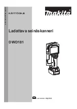
DWD181
Brand: Makita Pages: 195

fi-6000N
Brand: Fujitsu Pages: 2

Fi-5110EOX2 - ScanSnap! - Document Scanner
Brand: Fujitsu Pages: 2

FI-5900C
Brand: Fujitsu Pages: 4

FI-4860C2
Brand: Fujitsu Pages: 2


