

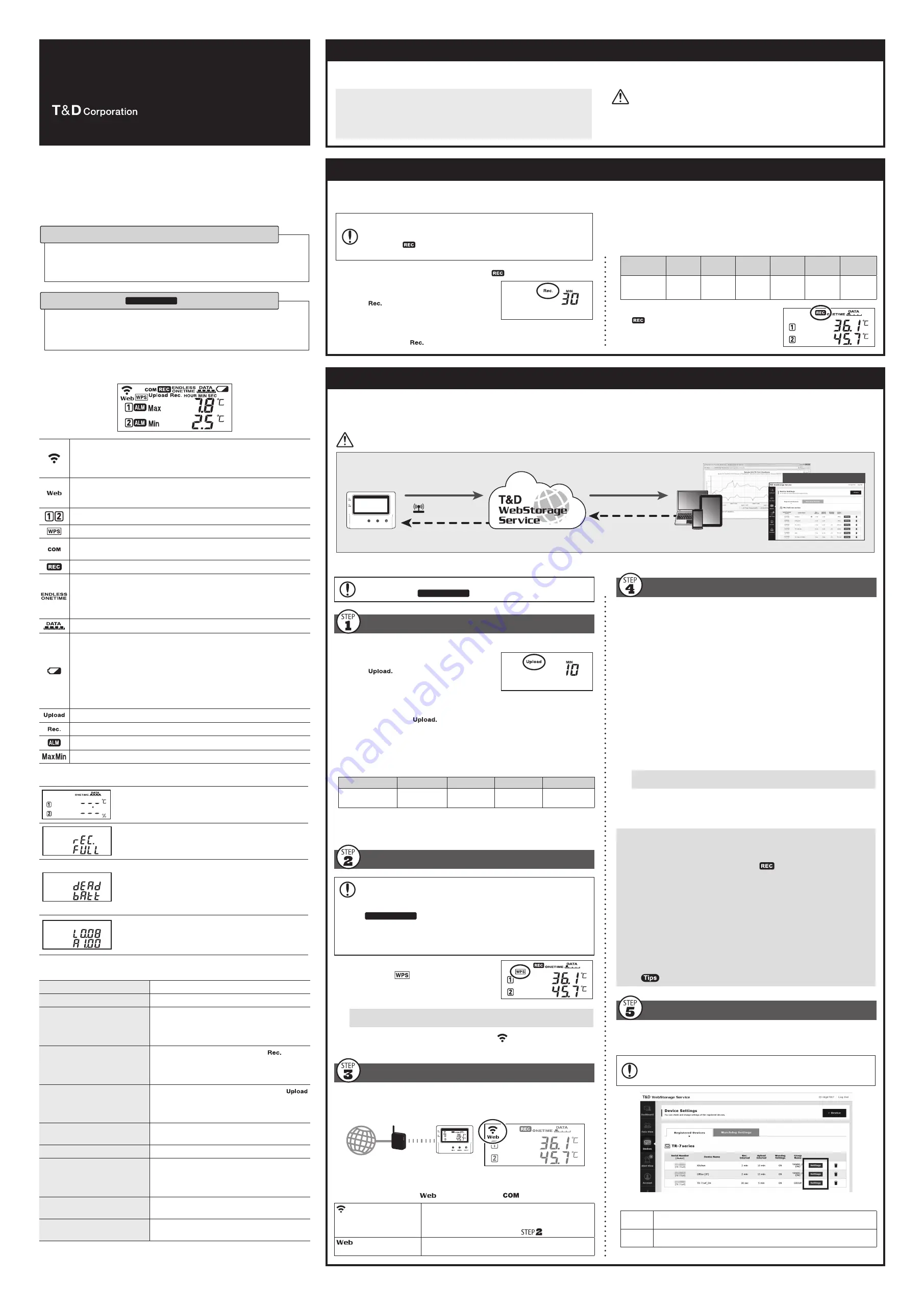
Automatic Data Upload to the Cloud
The auto-upload function enables TR7 series loggers to automatically upload recorded data to the free cloud storage service "T&D WebStorage Service".
The uploaded data is available for viewing from a web browser.
The factory default setting is OFF (no auto-upload). Please follow the steps below to change the setting.
Please read the "T&D WebStorage Service" License Agreement carefully before making settings. Making Auto-upload Settings indicates your acceptance of this
Agreement.
Auto-upload of Recorded Data
Cloud
Wireless/Wired LAN
View with a Web Browser
Graph Display
Download Data
Setup
Apply Settings
• This procedure requires Internet access via wireless LAN.
• Old data that exceeds the storage period will be deleted from "T&D WebStorage Service". Please check the details at T&D WebStorage Service License Agreement > Service Details.
If you wish to use a static IP address instead of DHCP, make network settings
with the software.
See reverse side.
Making Auto-Upload Settings
.
Press the <INTERVAL> button twice to display
the auto-upload interval.
.
While
is displayed, press-and-hold the
<INTERVAL> button until the interval time
flashes.
.
Press <INTERVAL> again to select the interval
time. Each press changes the interval as follows:
Auto-upload Intervals (
): OFF / 1, 2, 5, 10, 15, 20, 30 MIN / 1, 2, 3, 4, 6, 12, 24 HOUR
.
The interval time will stop flashing and the display will return to the normal
measurement mode, confirming that it is set.
Ref: Auto-Upload Intervals & Corresponding Estimated Battery Life
In general, the shorter the upload interval, the shorter the battery life.
Upload Interval
min
0 min
hr
hrs or more
Battery Life
About 10 days
About 2
months
About 1 year
About 15
months
• All estimates are based on operations carried out with a new battery and are in no way a
guarantee of actual battery life.
• When Auto-upload is used frequently on TR71A, the measurement of the internal sensor
may rise by around 0.3° C.
Making Wireless LAN Settings
To use the WPS feature, make sure to select WPS2-PSK(AES) or disable wireless
security in your access point settings. Wireless LAN settings using WPS may not
be possible depending on the supported features or settings of your wireless
LAN access point. In this case, please make wireless network settings on PC.
See reverse side.
The following information is required:
• Network Name (SSID)
• Security (WEP 64bit/128bit, WPA-PSK (TKIP), WPA2-PSK (AES))
• Password (Network Key)
.
Press the <PWR> and <DISPLAY> buttons
together until
appears on the LCD screen.
.
Set your wireless LAN access point to "WPS"
mode.
For details about Wireless LAN Access Point settings, refer to the user manual for
that access point.
.
When the setup is successfully completed, the
mark on the LCD display
will turn ON.
Checking Connection Status
Place the logger in the desired measurement location where Internet access is
available.
Connection Status Indicators
Internet
Wireless LAN
Access Point
Press the <REC/STOP> button to immediately send the recorded data to
"T&D WebStorage Service" without waiting for the next transmission. If the
transmission is successful,
will remain ON after
turns OFF.
is OFF or blinking:
Unable to connect to the wireless network.
Try changing the measurement location or adjusting the
distance between the logger and the access point, and
make the wireless LAN settings in
again.
is blinking:
Internet connection failed.
Please check the access point’ s internet connection.
Viewing Recorded Data
In order to view the recorded data on a web browser, it is necessary to register
devices to T&D WebStorage Service in advance.
.
Access "T&D WebStorage Service" from the web browser.
https://www.webstorage-service.com/
.
Click [Create Account] to go to the registration page, and follow the direc-
tions to complete the registration. If you already have your User ID, go to the
next step.
.
Login by entering the registered User ID and Password.
.
Click [Devices] in the left menu to open the Device Settings window.
.
Clicking the [+Device] button will take you to the Add a Device page.
.
Enter the serial number and registration code* for the target logger, then
click [Add].
* The registration code can be found on the supplied Registration Code Label.
.
After data is sent to either by auto-upload or by pressing the <REC/STOP>
button on the logger, the added device and its measurements will appear in
the [Data View] window.
Troubleshooting Tips
If measurements are not displayed:
Check the screen of the logger and make sure
is ON; If not, press-and-hold
<REC/STOP> to start recording. See “Recording Interval Setting above.
If the display of measurements is not refreshed:
Try making the recording interval shorter. If the recording interval is set to longer
than the upload interval, the same measurement is displayed until the next
recording occurs and the new data is uploaded.
If you lose your registration code label:
Open the software "TR7 for Windows" and connect your logger via USB to the
computer. The connected logger and its information will appear in the left boxes of
the main window. The registration code can be found here.
If you wish to save recorded data to PC:
Use "T&D Graph" that is available for download from the T&D Website.
See
on the reverse side.
Changing Device Settings
It is possible to change device settings by using "T&D WebStorage Service".
In the Device Settings window click the [Settings] button to open the settings box.
Make the necessary changes and click [Send Settings].
The setting changes will not be actually applied until communication occurs be-
tween the logger and "T&D WebStorage Service". By pressing the <REC/STOP>
button on the logger, however, settings can be applied immediately.
Setting Items which can be set or changed:
Device
Info
Device Name, Group Name, Recording Interval, Recording Mode, Auto-
Upload Interval, Time Difference, Temperature Unit, Channel Name
Warning
Settings
Lower Limit, Upper Limit, Sensor Warning, Judgement Time, Battery Warning
TR Series Thermo Recorder
TR A/TR A/TR A-S
User's Manual
tandd.com
© Copyright T&D Corporation. All rights reserved. 2021.04 165049300XX (Xth Edition)
In this document, TR71A, TR72A and TR72A-S are collectively referred to as
the “TR7A Series” or simply as the “device” or “logger” .
How to Use
There are mainly two ways to set up the device and manage the recorded data as
follows.
By using wireless LAN, the logger automatically uploads recorded data to the cloud
storage. It enables the viewing of uploaded data and the changing of settings on your
PC, smartphone and tablet.
Via Cloud: Automatic Data Upload
Make settings and download data by using the USB connection and PC software.
• If you are using the TR71A for vaccine storage and management, please follow this
method.
Via PC: Setup and Download
See reverse side.
Marks on LCD Screen
Wireless LAN
ON : Connected to the wireless network. (Signal strength: 1 to 3 bars)
BLINKING : Unable to connect to the wireless network.
OFF : Wireless LAN Settings are not made or Auto-Upload is “OFF” .
ON : Connected to the server.
BLINKING : Unable to connect to the server.
OFF : Wireless LAN Settings are not made or Auto-Upload is “OFF” .
Displayed Measurement Channel
ON : Wireless LAN Setup using WPS Possible
ON : Connected via Bluetooth or USB.
BLINKING : Bluetooth or USB communication in Progress
ON : Recording in Progress
ENDLESS : Upon reaching the logging capacity of 30,000 readings, the
oldest data is overwritten and recording continues.
ONETIME : Upon reaching the logging capacity of 30,000 readings, record-
ing automatically stops.
Cannot be set or changed using buttons on the logger.
Amount of Recorded Data in Device
Battery Warning Mark
BLINKING : Indicates low battery
ON : Wireless and Bluetooth communication will stop. (Recording will
continue.)
• Replacing the batteries while this is displayed will allow recording to continue uninterrupted. Please
change the batteries as soon as possible when you see this mark.
• If + (plus) and – (minus) are mistaken, or if the battery ter and – are shorted, the recorded
data that is stored in the device will be lost.
• The logger will stop measuring and recording data after about 3 minutes of battery removal. When
replacing batteries, install new batteries as quickly as possible.
Auto Upload Interval
Recording Interval
BLINKING : Indicates either upper/lower limit error or sensor error
Maximum and Minimum Readings
Messages on LCD Screen
Indicates a sensor error (No sensor connected, improper
connection, damaged, etc.)
Recording Full (Recording Stopped)
This appears when the logging capacity (30,000 readings)
is reached in “ONETIME” mode.
Dead Battery
If you take no action after the battery warning mark
appears on the display, the logger will show this message
and stop recording data.
The logger will then turn off the LCD display and reset the internal clock. If you
change the batteries at this point, it is still possible to download all saved
recorded data. The recording cannot be continued.
Upper part : Bootloader Version
Lower part : Firmware Version
This appears immediately after the power is turned on.
Button Operations
Power ON/OFF
Press-and-hold*
1
the <PWR> button.
Start/Stop Recording
Press-and-hold*
1
the <REC/STOP> button.
Check Recording Interval /
Upload Interval
Press the <INTERVAL> button.
With each pressing of the button, the display will
switch between the recording interval (Rec.) and
the upload interval (Upload).
Recording Interval Setting
Press the <INTERVAL> button. While
is
displayed, press-and-hold the <INTERVAL>
button until the interval time flashes. Press
<INTERVAL> again to select the interval time.
Upload Interval Setting
Press the <INTERVAL> button twice. While
is displayed, press-and-hold the <INTERVAL>
button until the interval time flashes. Press
<INTERVAL> again to select the interval time.
Transmit Data and Settings to
"T&D WebStorage Service"
Press the <REC/STOP> button.
Cancel Communication
Press the <PWR> button.
Switch Display Items and Pattern
(Fixed or Alternating Display)
Press the <DISPLAY> button to switch the display:
Ch1/Ch2 current values (fixed) → Ch1 Max/Min
values (fixed) → Ch2 Max/Min values (fixed) →
alternating display
Clear Max/Min (and ALM)
While Max/Min (and ALM) are displayed (in fixed
display), press-and-hold*
1
the <DISPLAY> button.
Wireless LAN Settings using WPS Press-and-hold*
1
<PWR> and <DISPLAY>
together.
*1. "Press-and-hold" means to hold the button down for about two seconds.
*2. Recording Interval setting cannot be changed while a recording session is in progress.
Recording Interval Setting
Install the batteries and sensor(s) in the logger, and make sure the LCD is displaying measurements.
The factory default setting for the recording interval is 10 minutes. Follow the procedure below to change this setting.
• Skip this setting if you don't need to change the recording interval.
• Upon the start of recording, all previously recorded data in the logger will be
deleted.
• Note: When
is ON (recording in progress), the logger cannot be turned
off, nor can the recording interval be changed.
.
Press-and-hold the <REC/STOP> button until
turns OFF (recording stops).
.
Press the <INTERVAL> button.
.
While
is displayed, press-and-hold the
<INTERVAL> button until the interval time
flashes.
.
Press the <INTERVAL> button again to select the interval time.
Recording Intervals(
) 1, 2, 5, 10, 15, 20, 30 SEC / 1, 2, 5, 10, 15, 20, 30, 60 MIN
.
When the desired recording interval appears, stop pressing the button.
Within a few seconds, the display will return to measurement mode to
indicate the recording interval is set.
Ref: Recording Intervals & Estimated Maximum Recording Times
Recording
Interval
1 sec
30 sec
5 min
10 min
(default)
15 min
60 min
Estimated
Time
About 8
hours
About 10
days
About 100
days
About 200
days
About 1
year
About 3.5
years
.
Press-and-hold the <REC/STOP> button until
turns ON (recording restarts).
For the Users of TR A
The TR71A has a “Vaccine Mode” setting that is suitable for such as vaccine storage and monitoring, which require strict temperature management. When
this mode is enabled, the following features are available:
• Warning Judgement Time :
0 sec. (immediate judgement)
• Auto Reset Max/Min Values
Monitor and record maximum and minimum temperatures for the day.
• CSV File Created upon Data Download
Manage reports on the daily maximum and minimum temperatures and total time out of range.
To use the TR A for vaccine management, please read the reverse side of
this document carefully, and make settings in “Vaccine Mode” using the
"TR for Windows" software.
* The button operations (such as recording interval, auto-upload interval, and wireless
LAN settings) can also be configured with this software.
Rec Interval
Auto Upload Interval


