background image


Document Revision:   1.A 

Auto Discovery 

Template Revision:  3 


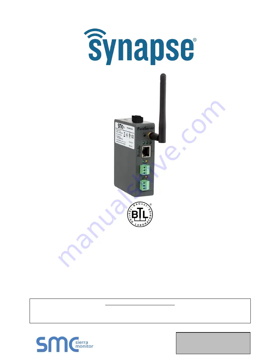
BMS Gateway BMS-GW (ProtoAir FPA-W44)  

Start-up Guide 

For Interfacing the SimplySNAP Site Controller 

(SS420/450) 

To Building Automation Systems:  

BACnet MS/TP, BACnet/IP, Modbus RTU and Modbus TCP/IP  


APPLICABILITY & EFFECTIVITY


Explains BSM-GW/ProtoAir hardware and how to install it. 

The instructions are effective for the above as of February 2019. 

Summary of Contents for BMS-GW Series

Page 1: ...rt up Guide For Interfacing the SimplySNAP Site Controller SS420 450 To Building Automation Systems BACnet MS TP BACnet IP Modbus RTU and Modbus TCP IP APPLICABILITY EFFECTIVITY Explains BSM GW ProtoAir hardware and how to install it The instructions are effective for the above as of February 2019 ...

Page 2: ... ProtoAir product Sierra Monitor Corporation does not provide direct support If Synapse Wireless needs to escalate the concern they will contact Sierra Monitor Corporation for assistance Support Contact Information Synapse Wireless 6723 Odyssey Drive Huntsville Alabama 35806 Customer Service 877 982 7888 Website www synapsewireless com Additionally a ticket can be opened at www synapse wireless co...

Page 3: ...S GW ProtoAir 3 pin RS 485 R2 port to the field protocol cabling Section 4 1 4 Connect power to the BMS GW ProtoAir s 3 pin connector Section 4 4 5 Connect a PC to the BMS GW ProtoAir via Ethernet cable or by the BMS GW ProtoAir s Wi Fi Access Point Section 5 6 Set the field protocol settings via the Web Configurator Section 7 1 7 Use the Discovery function to configure the BMS GW ProtoAir and to ...

Page 4: ...s 19 6 1 3 Update Wi Fi Client Settings 20 7 Configure the ProtoAir 21 7 1 Select BMS Protocol and Configure Settings 21 7 1 1 BACnet Settings Additional Information 22 7 1 1 1 Setting the MAC Address for the BACnet MS TP Network 22 7 1 1 2 Set the ProtoAir BACnet Device Instance 23 7 1 2 Modbus Settings Additional Information 24 7 1 2 1 Setting the Modbus Slave ID 25 7 2 Discover Devices Connecte...

Page 5: ...ieldServer as SSL TLS Client 44 Appendix B 1 2 1 Simple Secure Client Configuration 44 Appendix B 1 2 2 Limit Server Access 44 Appendix B 1 2 3 Certificate Validation Options 44 Appendix B 1 2 4 Set up Client Certificate 44 Appendix B 2 Updating Firmware 45 Appendix B 3 BACnet Setting Network_Number for More Than One ProtoAir on the Subnet 45 Appendix B 4 Securing ProtoAir with Passwords 46 Append...

Page 6: ... ID 25 Figure 17 Modbus TCP IP Settings Window Using Slave ID Offset 25 Figure 18 Discovery Window 26 Figure 19 Discovering Devices 26 Figure 20 The Device Tree 27 Figure 21 View Change Parameters on a Point 27 Figure 22 View Edit Node Parameters 28 Figure 23 Saving Configurations 28 Figure 24 Saved Configurations 28 Figure 25 Modbus Map Window 29 Figure 26 Saved Configurations 29 Figure 27 Clear ...

Page 7: ...symbol that indicates that a product has passed a series of rigorous tests conducted by an independent laboratory which verifies that the product correctly implements the BACnet features claimed in the listing The mark is a symbol of a high quality BACnet product Go to www BACnetInternational net for more information about the BACnet Testing Laboratory Click here for the BACnet PIC Statement ...

Page 8: ...P Modbus TCP IP and Modbus RTU It is not necessary to download any configuration files to support the required applications The ProtoAir is pre loaded with tested profiles configurations for the supported devices FPA W44 Connectivity Diagram The ProtoAir can connect with Sierra Monitor s SMC Cloud The SMC Cloud allows technicians the OEM s support team and Sierra Monitor s support team to remotely...

Page 9: ...rts RS 485 Ethernet RS 485 3 2 Configuring Device Communications The device needs to be on the same IP subnet as the ProtoAir and the configuration PC Record the following device information o IP Address o IP Port o Username o Password NOTE This information is required for Section 7 3 3 Attaching the Antenna Wi Fi Antenna Screw in the Wi Fi antenna to the front of the unit as shown in Figure 41 NO...

Page 10: ... the RS 485 network wires to the 3 pin RS 485 connector on the R2 port Figure 2 o Use standard grounding principles for RS 485 GND See Section 6 for information on connecting to an Ethernet network BMS Wiring ProtoAir Pin Pin Assignment RS 485 Pin 1 RS 485 RS 485 Pin 2 RS 485 Pin 3 RS 485 GND Figure 2 Connection from ProtoAir to RS 485 Field Network G ...

Page 11: ...tor is 510 ohms which is in line with the BACnet spec It should only be enabled at one point on the bus for example on the field port were there are very weak bias resistors of 100k Since there are no jumpers many gateways can be put on the network without running into the bias resistor limit which is 500 ohms NOTE See www ni com support serial resinfo htm for additional pictures and notes NOTE Th...

Page 12: ...ure 4 Termination resistor is also used to reduce noise It pulls the two lines of an idle bus together However the resistor would override the effect of any bias resistors if connected NOTE The R1 and R2 DIP Switches apply settings to the respective serial port NOTE If the gateway is already powered on DIP switch settings will not take effect unless the unit is power cycled R1 Termination Resistor...

Page 13: ...hould be added to the power supply of the host system A safety margin of 25 is recommended Figure 5 Required Current Draw for the ProtoAir Apply power to the ProtoAir as shown below in Figure 6 Ensure that the power supply used complies with the specifications provided in Appendix C 1 The ProtoAir accepts 12 24VDC or 24VAC on pins 4 and 5 Frame GND should be connected Power to ProtoAir ProtoAir Pi...

Page 14: ... Changing the Subnet of the Connected PC The default IP Address for the ProtoAir is 192 168 1 24 Subnet Mask is 255 255 255 0 If the PC and ProtoAir are on different IP networks assign a static IP Address to the PC on the 192 168 1 xxx network For Windows 10 Find the search field in the local computer s taskbar usually to the right of the windows icon and type in Control Panel Click Control Panel ...

Page 15: ...ity status is green then the IP Address doesn t need to be changed the ProtoAir is already on the same subnet Skip to the next section Select Network Settings in the Configure Device window Modify the IP Address N1 IP Address field of the gateway Ethernet port o Change additional fields as needed NOTE If the gateway is connected to a router the Default Gateway field of the gateway should be set to...

Page 16: ... connection to the ProtoAir with Wi Fi To connect to the ProtoAir Wi Fi Access Point Click the icon found in the bottom right corner of the computer screen to open the available Wireless Network Connections Select the desired ProtoAir and click Connect Enter the Security key The default is 12345678 The available Wireless Network Connection menu should now show that the computer is connected to the...

Page 17: ...assigned IP Address can be discovered using the FS Toolbox utility See Appendix A 1 for instructions From the Web Configurator landing page click the Network Settings tab to open the Network Settings page for the ProtoAir Configure the network settings of the ProtoAir using the following methods When using the Ethernet port to connect to the local network Section 6 1 2 When connecting the ProtoAir...

Page 18: ...le NOTE The default Primary Connection is Ethernet To change the primary connection when both Ethernet and Wi Fi Client connections are available Select the desired option from the Primary Connection drop down menu Click Save then click on Refresh to restart the ProtoAir and activate the new settings NOTE If using Wi Fi Client and not Ethernet change Primary Connection to Wi Fi Figure 9 Common Net...

Page 19: ...d via these fields IP Address Netmask Default Gateway and Domain Name Server1 2 NOTE If connected to a router set the Default Gateway to the same IP Address as the router Click Save then click on Refresh to restart the ProtoAir and activate the new IP Address NOTE If the ProtoAir was open in a browser the browser will need to be updated with the new Wi Fi details before the ProtoAir will be access...

Page 20: ... the Wi Fi SSID and Wi Fi Password for the local wireless access point Enable DHCP to automatically assign all Wi Fi Client network settings or manually modify the setting using the fields immediately below IP Address Network etc NOTE If connected to a router set the IP gateway to the same IP Address as the router Click Save then click on Refresh to restart the gateway and activate the new Wi Fi s...

Page 21: ...ttings Go back to the Discovery and Configuration tab and press the BMS Settings button to view change the Building Management System BMS Settings Select BACnet IP BACnet MS TP Modbus TCP IP or Modbus RTU protocols Edit settings as needed Once completed click Save and allow the ProtoAir to restart Figure 12 Select BMS Protocol ...

Page 22: ...0 38400 or 76800 7 1 1 1 Setting the MAC Address for the BACnet MS TP Network NOTE Only 1 MAC Address is set for the ProtoAir regardless of how many devices are connected to the ProtoAir Set the BACnet MS TP MAC Address of the ProtoAir to a value between 1 to 127 MAC Master Addresses this is so that the BMS Front End can find the ProtoAir via BACnet auto discovery NOTE Never set a BACnet MS TP MAC...

Page 23: ...ance is a BACnet Node ID which is obtained by the network administrator All the devices connected to the ProtoAir will be under the same BACnet Device Instance NOTE The default BACnet Device Instance is 11 The values allowed for a BACnet Device Instance can range from 1 to 4 194 303 To assign a specific Device Instance change the Device Instance value as desired Figure 14 BACnet IP Settings Window...

Page 24: ...ails into the web configuration as seen in Figure 15 or Figure 16 below Connection Modbus RTU only Select the physical port to use Partial Data Response Modbus TCP IP only If a partial data response is received on the SimplySNAP coms select how the ProtoAir will respond to the Modbus front end Figure 15 Modbus RTU Settings Window ...

Page 25: ...e ID Offset will not be used In this setting only one Modbus server node willl be created If Slave ID is not used input a dash into the Slave ID field the Slave ID Offset will be used to generate multiple Modbus server nodes Figure 16 Modbus TCP IP Settings Window Using Slave ID Figure 17 Modbus TCP IP Settings Window Using Slave ID Offset ...

Page 26: ...r the SimplySNAP Site Controller Section 3 2 After entering details click on Start Discovery and the discovery progress bar will display o Discovery may take a few minutes depending on the number of points to discover After the discovery process is complete the device tree will appear see Appendix B 8 for device tree structure details Figure 18 Discovery Window Figure 19 Discovering Devices ...

Page 27: ...ey have not been configured for protocol conversion When viewing points or parameters containing points click inside the checkbox to select or deselect items for protocol conversion NOTE Clicking a checkbox will also select all points nested under that item o By clicking on a point the endpoint parameters for that point will be shown and depending on the protocol some fields may be editable NOTE I...

Page 28: ...ral minutes When this process is complete a window will appear to request a system restart click restart o The checkboxes of the selected points will now be filled in to show they are configured o Protocol specific reference fields such as BACnet Instance and Modbus Node ID information will also populate for all configured points devices NOTE This configuration method is the same for all protocols...

Page 29: ... for the entire configuration or click on a specific device to view the map for just the selected device To view or download the Modbus mapping click the Download or View links o Click View to open a window that lists the Modbus data points NOTE Find specific points using the search bars above each data element o Click Download to download a CSV file of the Modbus data points to the local PC s def...

Page 30: ...click on Clear Configuration An additional option to clear all other device configurations is also available After clicking on the Clear Restart button the window will state Configuration cleared Restarting After this process is complete the ProtoAir will automatically restart Figure 27 Clear Configuration Window ...

Page 31: ...tract the executable file and complete the installation Connect a standard Cat 5 Ethernet cable between the user s PC and ProtoAir Double click on the FS Toolbox Utility and click Discover Now on the splash page Check for the IP Address of the desired gateway If correcting the IP Address of the gateway click the settings icon on the same row as the gateway then click Network Settings change the IP...

Page 32: ...errors showing on the Connections page refer to 0 to check the wiring and settings NOTE The FieldPoP button see Figure 29 allows users to connect to the SMC Cloud Sierra Monitor s device cloud solution for IIoT The SMC Cloud enables secure remote connection to field devices through a FieldServer and its local applications for configuration management maintenance For more information about the SMC ...

Page 33: ...ice address o Visual observations of LEDs on ProtoAir Appendix A 4 o Verify wiring o Verify the device was discovered Section 7 Field COM problems o Visual observations of LEDs on the ProtoAir Appendix A 4 o Verify IP Address setting o Verify wiring NOTE If the problem still exists a Diagnostic Capture needs to be taken and sent to technical support Appendix A 5 ...

Page 34: ... in the error screen of the FS GUI interface to support for evaluation PWR This is the power light and should always show steady green when the unit is powered TX The TX LED will flash when a message is received on the serial port on the 3 pin connector If the serial port is not used this LED is non operational TX1 applies to the R1 connection while TX2 applies to the R2 connection RX The RX LED w...

Page 35: ...iagnostic capture utilities are embedded in the FS GUI web interface Starting a diagnostic capture takes a snapshot of the loaded configuration files and a log of all the communications over a specified period of time This works for both serial and Ethernet connections NOTE The information in the zipped files contains everything support needs to quickly resolve problems that occur on site Appendix...

Page 36: ...y ProtoAir Start up Guide Page 36 of 52 Step 1 Take a Log o Click on the diagnose icon of the desired device o Ensure Full Diagnostic is selected this is the default NOTE If desired the default capture period can be changed ...

Page 37: ...to finish then the Diagnostic Test Complete window will appear Step 2 Send Log o Once the Diagnostic test is complete a zip file is saved on the PC o Choose Open to launch explorer and have it point directly at the correct folder o Contact technical support for delivery instructions and send the Diagnostic zip file ...

Page 38: ...pture will accelerate diagnosis of the problem Open the FieldServer FS GUI page Click on Diagnostics in the Navigation panel Go to Full Diagnostic and select the capture period Click the Start button under the Full Diagnostic heading to start the capture o When the capture period is finished a Download button will appear next to the Start button Click Download for the capture to be downloaded to t...

Page 39: ... Good 80dBm Weak Figure 33 Wi Fi Signal Strength Listing NOTE If the signal is weak or spotty try to improve the signal strength by checking the antenna and the ProtoAir position Appendix A 7 Factory Reset Instructions For instructions on how to reset a FieldServer back to its factory released state see ENOTE FieldServer Next Gen Recovery ...

Page 40: ...e software needs to be modified to allow the PC to register bridges on SMC Cloud NOTE This problem is specific to KES10 Kaspersky 2017 does not have this problem To fix the problem the ProtoAir http 192 168 100 85 in Figure 31 must be set as a trusted URL to the Web Anti Virus Settings as shown below Figure 34 Kaspersky ES10 Settings Figure 35 Web Anti Virus Trusted URLs ...

Page 41: ...e Secure Server Configuration Add TLS_Port parameter in the connections section of the configuration file and set to a port number between 1 65535 Connections Adapter Protocol TLS_Port N1 Modbus TCP 1502 This configuration sets the FieldServer to accept any incoming connection but will not request a client s certificate for verification This means that the FieldServer end point communication will ...

Page 42: ...he FieldServer with the following connection settings Connections Adapter Protocol TLS_Port Validate_Client_Cert Cert_Authority_File N1 Modbus TCP 1502 Yes my_authorized_clients pem This configuration has the FieldServer accept connections from clients who have the correct certificate The authority file is a collection of client certificates in PEM format This file can be edited using any text fil...

Page 43: ...ue is synonymously known as common name host name or domain etc The common name can be obtained by the following methods Ask the certificate issuer for the host name Use online tools to decode the certificate for example https www sslshopper com certificate decoder html If the program openssl is installed on the local PC then run the following command to get the common name openssl x509 in certifi...

Page 44: ...server s certificate against its own internal authority file before finalizing the connection By default this means the FieldServer will only establish connections to other FieldServers Remote_Node_TLS_Port Validate_Server_Cert Cert_Authority_File 1502 Yes my_authorized_servers pem The above configuration sets the FieldServer to use a specified PEM file to allow custom server connections The autho...

Page 45: ...and side do the following a Click on Setup b Click on File Transfer c Click on the General tab 5 In the General tab click on Choose Files and select the web img file extracted in step 1 6 Click on the orange Submit button 7 When the download is complete click on the System Restart button Appendix B 3 BACnet Setting Network_Number for More Than One ProtoAir on the Subnet For both BACnet MS TP and B...

Page 46: ...ccount has unrestricted access to the ProtoAir The User account can view any ProtoAir information but cannot make any changes or restart the ProtoAir The password needs to be a minimum of eight characters and is case sensitive If the password is lost click cancel on the password authentication popup window and email the password recovery token to technical support to receive a temporary password f...

Page 47: ...o allow connecting to the ProtoAir via Wi Fi Modify the Settings manually as needed via these fields Access Point SSID Access Point Password SSID Broadcast and Channel NOTE The default channel is 11 Click Save then click on Refresh to restart the ProtoAir and activate the Wi Fi settings NOTE If the ProtoAir was open in a browser via Wi Fi the browser will need to be updated with the new Wi Fi deta...

Page 48: ...mplySNAP BMS Gateway ProtoAir Start up Guide Page 48 of 52 Appendix B 6 Mounting The ProtoAir can be mounted using the DIN rail mounting bracket on the back of the unit Figure 40 DIN Rail Din Rail Bracket ...

Page 49: ...SimplySNAP BMS Gateway ProtoAir Start up Guide Page 49 of 52 Appendix B 7 Physical Dimension Drawing Figure 41 ProtoAir FPA W44 Dimensions R1 Serial Port Power Port Wi Fi Antenna Socket R2 Serial Port ...

Page 50: ... Start up Guide Page 50 of 52 Appendix B 8 Structure of the Device Tree The Device Tree is in the following structure ProtoAir IP Address o Device types List of devices connected to this ProtoAir List of device parameters For example ...

Page 51: ...sive Antenna Type SMA Encryption TKIP WPA AES Figure 42 Specifications Appendix C 1 1 Compliance with UL Regulations For UL compliance the following instructions must be met when operating ProtoAir The units shall be powered by listed LPS or Class 2 power supply suited to the expected operating temperature range The interconnecting power connector and power cable shall o Comply with local electric...

Page 52: ...application or on which original identification marks have been removed or altered This Limited Warranty also will not apply to interconnecting cables or wires consumables or to any damage resulting from battery leakage In all cases Sierra Monitor Corporation s responsibility and liability under this warranty shall be limited to the cost of the equipment The purchaser must obtain shipping instruct...

Reviews: