SwitchBee 1-M-SSR, Settings Manual
Looking for a comprehensive settings manual for the SwitchBee 1-M-SSR? Look no further! Download our free manual from manualshive.com to explore all the features and functionalities of this innovative product. With step-by-step instructions and detailed explanations, our manual will help you unleash the full potential of your SwitchBee 1-M-SSR.
Share
Download


Reviews:
No comments
Related manuals for 1-M-SSR

MSS
Brand: echoflex Pages: 4

ELIOS4YOU Pro
Brand: 4-noks Pages: 2

HRSD-2C
Brand: Hoymiles Pages: 2
Symbio
Brand: Toshiba Pages: 83

GSM GENIE
Brand: SABERTEK Pages: 25

Smart Monitor WFA001
Brand: Wallflower Pages: 2

ElahoAccess Interface
Brand: echoflex Pages: 8

ZL-100
Brand: ZLINK Pages: 11

ORM 2
Brand: Micos Pages: 4

NRA Biometric Holster
Brand: Jotto Gear Pages: 8

DOMO connexa
Brand: CISA Pages: 24

PHAST PLL-SW10
Brand: AMX Pages: 3
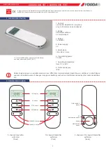
AURORA OVO 5RT
Brand: YOODA Pages: 4

TUXEDOW
Brand: Honeywell Home Pages: 56


