SABERTEK GSM GENIE, User Manual
Introducing the SABERTEK GSM GENIE, a revolutionary product designed to redefine communication. Unlock the true potential of this device with our comprehensive User Manual. Delve into its advanced features, troubleshooting tips, and step-by-step instructions. Download the free manual now from our website, your ultimate resource for user manuals.
Share
Download


Reviews:
No comments
Related manuals for GSM GENIE

modlet
Brand: ThinkEco Pages: 12
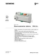
PXC3.E16A100A
Brand: Siemens Pages: 12

RDF Series
Brand: Siemens Pages: 28

OZW772 Series
Brand: Siemens Pages: 176

QAW740
Brand: Siemens Pages: 184

Desigo RXB
Brand: Siemens Pages: 476

Curtain U Rail
Brand: SwitchBot Pages: 93

41730
Brand: Monoprice Pages: 20

EASYPlug
Brand: tapHOME Pages: 2

IQ Smart Socket-PG
Brand: QOLSYS Pages: 8

Intelligent Fob
Brand: Wondrwall Pages: 12

VTi CELTIC DC
Brand: Vertilux Pages: 10

DualBrite SH-5318
Brand: Secure Home Pages: 8

RF-SECURE Bluetooth
Brand: Secure Pages: 8

GSS01
Brand: Geti Pages: 6

KNX 5001 Series
Brand: Gira Pages: 6

Control 9 Client
Brand: Gira Pages: 11

2096 00
Brand: Gira Pages: 48


