


SUSPA GmbH
Installation Instructions
English
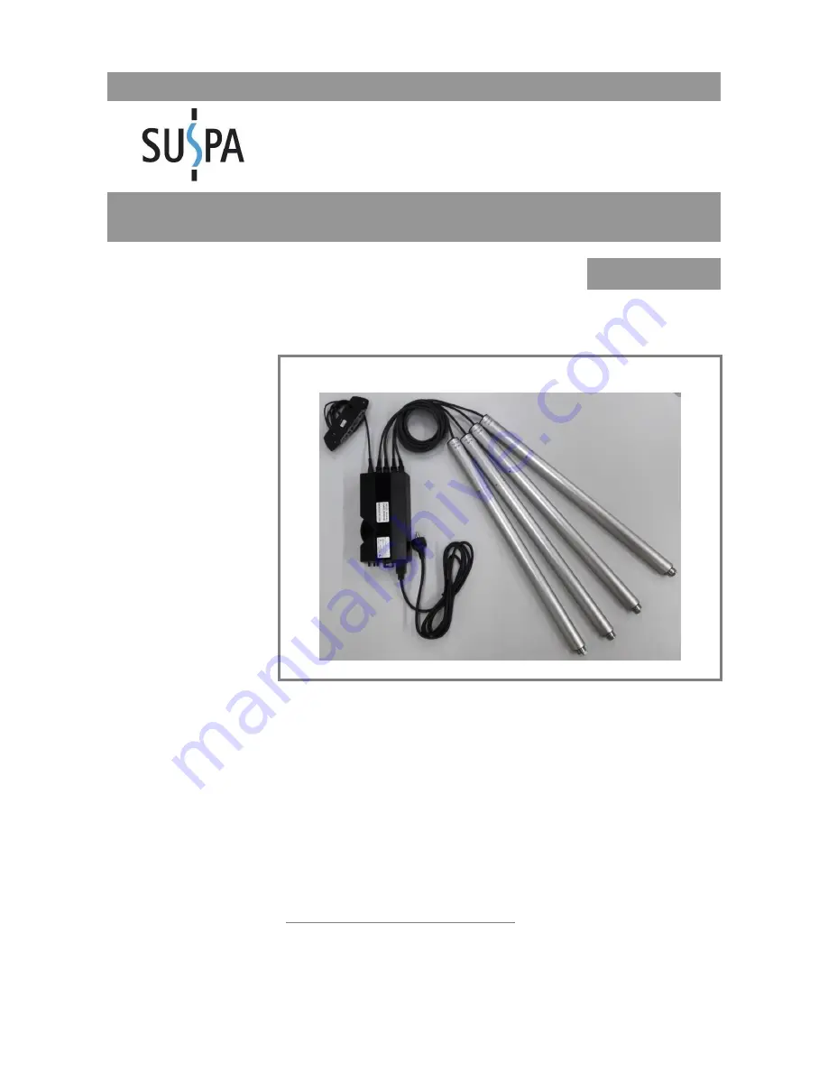
SUSPA Movotec SMS
Read installation instructions carefully before initial use!
Follow the safety instructions!
This partly completed machinery is intended to be incorporated into oth-
er machinery, other partly completed machinery/equipment or to be
joined with another framework so as to form a complete machine as
specified under the Machinery Directive. A conformity assessment proce-
dure must be carried out on the whole completed machine in accordance
with the Machinery Directive before it can be put into operation.
No revision service applies to this documentation. The current installation
instructions are available at
https://www.suspa.com/uk/downloads/
February 2018


