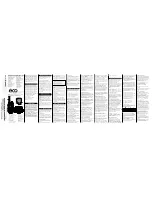
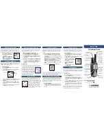
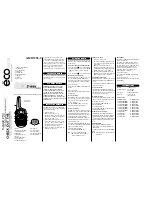
background image


MP_PS 

MID POWER 


Digital Radios 
37dBm per Band 


MP_PS User Manual 

Remote Unit 

Model No: PS-R2220708 


Summary of Contents for PS-R2220708

Page 1: ...MP_PS MID POWER Digital Radios 37dBm per Band MP_PS User Manual Remote Unit Model No PS R2220708 ...

Page 2: ...ying recording or otherwise without prior written permission from Sunwave All copyright confidential information patents design rights and all other intellectual property rights of whatsoever nature contained herein are and shall remain the sole and exclusive property of Sunwave The information furnished herein is believed to be accurate and reliable However no responsibility is assumed by Sunwave...

Page 3: ... Inspecting the Device 9 Installation Preparation 9 Site Investigation 9 Installation Tools 10 Torque Settings 10 Clearance 10 Installing the Access Unit AU 11 Accessories List 12 Rack Installation 12 Wall Installation 18 AU Mounting Dimension Spacing 21 RF Connection 22 Installing the Remote Unit MP_PS 23 MP_PS Accessories 23 Wall Installation Back on the Wall 24 Wall Installation Side on the Wal...

Page 4: ...Radio Sunwave MP_PS_User Manual 4 of 46 Contact us today www sunwave com cf_support sunwave com Optical Transceiver Module 45 Single Port Bidirectional SFP Transceiver 45 Dual Port SFP Transceiver 45 Optical Indicator 46 ...

Page 5: ...continuing violation This is NOT a CONSUMER device It is designed for installation by an installer approved by an ISED licensee You MUST have an ISED LICENCE or the express consent of an ISED licensee to operate this device Il ne s agit PAS d un dispositif CONSOMMATEUR Il est conçu pour être installé par un installateur agréé par un titulaire de licence ISED Vous devez avoir un LICENCE ISED ou le ...

Page 6: ...e must accept any interference including interference that may cause undesired operation of the device Le présent appareil est conforme aux CNR d Industrie Canada applicables aux appareils radio exempts de licence L exploitation est autorisée aux deux conditions suivantes 1 l appareil ne doit pas produire de brouillage et 2 l utilisateur de l appareil doit accepter tout brouillage radioélectrique ...

Page 7: ...g Marks The warning marks on the CrossFire shell should be kept clean readable and identifiable ALWAYS disconnect all lines and power connections before servicing or disassembling this equipment NEVER touch the surface after power on the devices For performance and safety reasons NEVER disassemble and remodel the devices ...

Page 8: ...iner 2 Immediately contact the transportation carrier and notify them of the damage 3 File a claim with the carrier once you determine the extent of any damage 4 Return it to SUNWAVE s nearest RMA facility and contact SUNWAVE for RMA processing Unpacking the Device If the container appears to be in satisfactory condition 1 Ensure both user and supplier representatives are in attendance during ship...

Page 9: ...ectangular 6 Ensure that the guide bar has not been damaged and the fittings and auxiliary parts are intact 7 Check that the silk screened images on the device are visible and intact Installation Preparation Site Investigation Before installation the installer should contact the project director to ensure that the site is suitable for installation Details required include information about the ins...

Page 10: ...ings Type M3 M6 M10 Specified Torques 0 6Nm 5Nm 50Nm Clearance You must ensure the following mounting clearances for mounting within a 19 rack cabinet Convection cooling Maintain 3U clearance between the bottom of the device and any other Maintain 3U clearance from the top surface of the device to the top of the rack FAN Cooling You can mount the fan between the bottom of the device and any other ...

Page 11: ...Mid POWER Digital Radio Sunwave MP_PS_User Manual 11 of 46 Contact us today www sunwave com cf_support sunwave com Installing the Access Unit AU ...

Page 12: ...even to avoid a hazardous condition The rack should safely support the combined weight of all the equipment and be securely anchored Installing the Access Unit in a climate controlled room with sufficient air circulation is recommended as the maximum ambient temperature is 50 C To install the Access Unit in the equipment rack 1 Attach the 19 mounting brackets at the front of the AU using 4 screws ...

Page 13: ...Mid POWER Digital Radio Sunwave MP_PS_User Manual 13 of 46 Contact us today www sunwave com cf_support sunwave com ...

Page 14: ...Mid POWER Digital Radio Sunwave MP_PS_User Manual 14 of 46 Contact us today www sunwave com cf_support sunwave com 2 Recommended attaching the sliding rails to rack Not included in delivery ...

Page 15: ...igital Radio Sunwave MP_PS_User Manual 15 of 46 Contact us today www sunwave com cf_support sunwave com 3 Place the AU in the rack and secure the AU using 2 screws M6 16 on both sides and the Phillips screwdriver ...

Page 16: ...ing if multiple AUs are installed in the same rack It is necessary to allow at least 3 rack units 132mm of free space below each unit for heat dissipation without fan installed or 1 rack unit 44mm of free space below each unit with fan occupied in the middle Otherwise the device temperature may rise and affect the service life of the device ...

Page 17: ...gital Radio Sunwave MP_PS_User Manual 17 of 46 Contact us today www sunwave com cf_support sunwave com 5 Connect and lock the power cable at the AU rear side 6 Connect and screw the ground wire at the AU rear side ...

Page 18: ... us today www sunwave com cf_support sunwave com Wall Installation To install the Access Unit on the wall 1 Rotate the handles 90 and attach them at the rear of the AU using 4 screws M3 6 per bracket and the Phillips screwdriver Observe the orientation of the brackets ...

Page 19: ...day www sunwave com cf_support sunwave com 2 Mark 4 x 6 8mm drilling holes sites for the hanger to be attached to the wall 3 Drill 4 holes at the marked sites using percussion drill and embed 4 10 plastic expansion pipes Note H 70mm Fasten the case with 4 M6 expansion bolt ...

Page 20: ...gital Radio Sunwave MP_PS_User Manual 20 of 46 Contact us today www sunwave com cf_support sunwave com 4 Connect and lock the power cable at the AU rear side 5 Connect and screw the ground wire at the AU rear side ...

Page 21: ...Mid POWER Digital Radio Sunwave MP_PS_User Manual 21 of 46 Contact us today www sunwave com cf_support sunwave com AU Mounting Dimension Spacing ...

Page 22: ...oss 50Ω coaxial cable for all coaxial connections and route the cables from the signal source or CPOI to the Active Combiner module 2 Connect the cables from the signal source to the QMA female connectors on the Active Combiner module on the back panel of the Access Unit Note Each Active Combiner module has four connectors to support up to four inputs AU Rear Panel Interfaces SN Interface Name Des...

Page 23: ...Mid POWER Digital Radio Sunwave MP_PS_User Manual 23 of 46 Contact us today www sunwave com cf_support sunwave com Installing the Remote Unit MP_PS MP_PS Accessories ...

Page 24: ...ntact us today www sunwave com cf_support sunwave com Wall Installation Back on the Wall 1 Attach and fasten the handle to the side of MP_PS with screws M6 14 using T5 Wrench 2 Attach and fasten the Bracket I to the back of MP_PS with screws M6 14 using T5 Wrench ...

Page 25: ...e position of the drilling holes in the mounting Bracket II Note R 13mm 4 Drill 4 holes at the marked positions Note H 70mm 5 Attach the dowels expansion screws or the like and fasten the Bracket II to the wall Tips use Bracket II as a reference to control each devices separation distance before hanging and locking MP_PS up ...

Page 26: ...Mid POWER Digital Radio Sunwave MP_PS_User Manual 26 of 46 Contact us today www sunwave com cf_support sunwave com 6 Hang the MP_PS on the mounting bracket II and fasten with nuts M10 ...

Page 27: ...Mid POWER Digital Radio Sunwave MP_PS_User Manual 27 of 46 Contact us today www sunwave com cf_support sunwave com 7 Fasten the Bracket I and II with screws M6 14 ...

Page 28: ...Mid POWER Digital Radio Sunwave MP_PS_User Manual 28 of 46 Contact us today www sunwave com cf_support sunwave com 8 Connect and lock the power cable 9 Connect and screw the ground cable ...

Page 29: ...Mid POWER Digital Radio Sunwave MP_PS_User Manual 29 of 46 Contact us today www sunwave com cf_support sunwave com 10 Connect and tighten the waterproof network cable ...

Page 30: ...Mid POWER Digital Radio Sunwave MP_PS_User Manual 30 of 46 Contact us today www sunwave com cf_support sunwave com 11 Connect and tighten the waterproof optical fibre ...

Page 31: ...Mid POWER Digital Radio Sunwave MP_PS_User Manual 31 of 46 Contact us today www sunwave com cf_support sunwave com Wall Installation Side on the Wall ...

Page 32: ...ual 32 of 46 Contact us today www sunwave com cf_support sunwave com 1 Attach and fasten the handle to the side of MP_PS with screws M6 14 using T5 Wrench 2 Attach and fasten the Bracket I to the left side of MP_PS with screws M6 14 using T5 Wrench ...

Page 33: ...e position of the drilling holes in the mounting Bracket II Note R 13mm 4 Drill 4 holes at the marked positions Note H 70mm 5 Attach the dowels expansion screws or the like and fasten the Bracket II to the wall Tips use Bracket II as a reference to control each devices separation distance before hanging and locking MP_PS up ...

Page 34: ...Mid POWER Digital Radio Sunwave MP_PS_User Manual 34 of 46 Contact us today www sunwave com cf_support sunwave com 6 Hang the MP_PS on the mounting bracket II and fasten with nuts M10 ...

Page 35: ...Mid POWER Digital Radio Sunwave MP_PS_User Manual 35 of 46 Contact us today www sunwave com cf_support sunwave com 7 Fasten the Bracket I and II with screws M6 14 ...

Page 36: ...Mid POWER Digital Radio Sunwave MP_PS_User Manual 36 of 46 Contact us today www sunwave com cf_support sunwave com 8 Connect and lock the power cable 9 Connect and screw the ground cable ...

Page 37: ...Mid POWER Digital Radio Sunwave MP_PS_User Manual 37 of 46 Contact us today www sunwave com cf_support sunwave com MP_PS Wall Mounting Dimension Spacing ...

Page 38: ...ve com Pole Installation 1 Install the handle and Bracket I to the back of MP_PS 2 Install the bracket II and Bracket III to the pole 3 Hang the MP_PS on the mounting bracket and fasten with nuts M10 4 Connect the ground cable and power cable Note The diameter of Pole shall not be over 110mm or less than 55mm ...

Page 39: ...Mid POWER Digital Radio Sunwave MP_PS_User Manual 39 of 46 Contact us today www sunwave com cf_support sunwave com Rack Installation ...

Page 40: ...unwave MP_PS_User Manual 40 of 46 Contact us today www sunwave com cf_support sunwave com 1 Attach and fasten the Bracket III to the Standard 19 Rack with screws Note Please purchase Bracket III for rack installation separately ...

Page 41: ...anual 41 of 46 Contact us today www sunwave com cf_support sunwave com 2 Attach and fasten the handle to the side of MP_PS with screws M6 14 using T5 Wrench 3 Attach and fasten the Bracket I to the back of MP_PS with screws M6 14 using T5 Wrench ...

Page 42: ...Mid POWER Digital Radio Sunwave MP_PS_User Manual 42 of 46 Contact us today www sunwave com cf_support sunwave com 4 Hang the MP_PS on the mounting bracket and fasten with nuts M10 ...

Page 43: ...Mid POWER Digital Radio Sunwave MP_PS_User Manual 43 of 46 Contact us today www sunwave com cf_support sunwave com 5 Connect the ground cable and power cable 6 Connect and screw the ground cable ...

Page 44: ...Mid POWER Digital Radio Sunwave MP_PS_User Manual 44 of 46 Contact us today www sunwave com cf_support sunwave com MP_PS Wall Mounting Dimension Spacing ...

Page 45: ...r optical modules The indicator turns to green when optical modules are plugged in ports and synchronized When connection is down or there is no optical module in port the indicator remains red The single port SFP modules have to be used in pairs Dual Port SFP Transceiver The optical connector unit includes an optical module and optical fibre The Figure below shows that when using dual port SFP mo...

Page 46: ...rrows represent the synchronization status of the upper and lower optical modules When a pair of optical modules are synchronized both uplink and downlink the indicators turn green as shown in the right pair of indicators in Figure below When the optical module is unplugged or not synchronized the indicators are red as shown in the left pair of indicators Check whether both indicators turn green a...

Reviews: