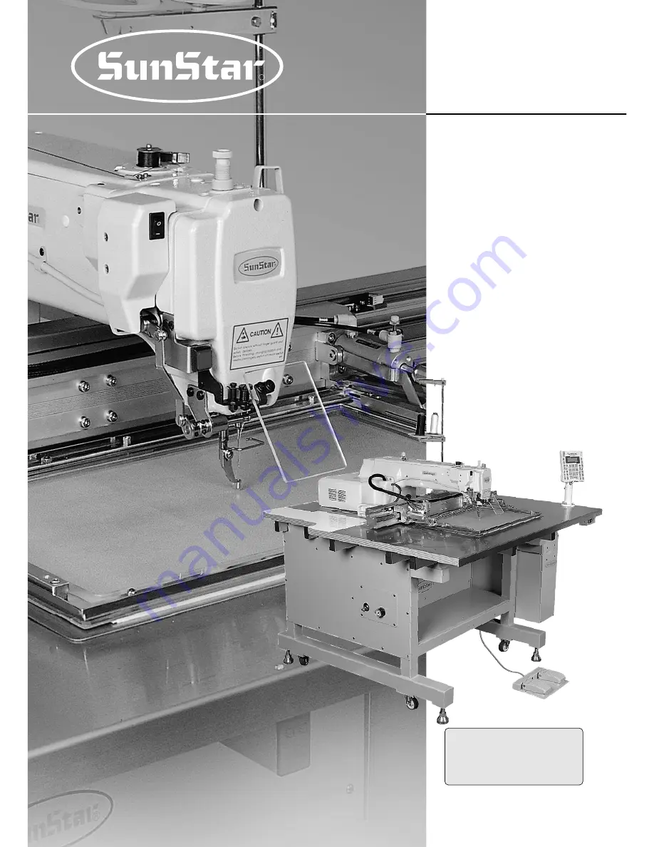
background image

R

SSUUNNSSTTAARR M

MAACCHHIINNEERRYY CCOO..,, LLTTDD

E

Elle

ec

cttrro

on

niic

ca

allllyy C

Co

on

nttrro

olllle

ed

d

P

Pa

atttte

errn

n S

Se

ew

wiin

ng

g M

Ma

ac

ch

hiin

ne

e

USER

S

MANUAL

SPS/A-3020 5030 SERIES

1) FOR AT MOST USE WITH EASINESS, 

PLEASE CERTAINLY READ THIS MANUAL

BEFORE STARTING USE.

2) KEEP THIS MANUAL IN SAFE PLACE 

FOR REFERENCE WHEN THE MACHINE 

BREAKS DOWN.

MME-050228

Summary of Contents for SPS/A-3020 5030 SERIES

Page 1: ...ly y C Co on nt tr ro ol ll le ed d P Pa at tt te er rn n S Se ew wi in ng g M Ma ac ch hi in ne e USER S MANUAL SPS A 3020 5030 SERIES 1 FOR AT MOST USE WITH EASINESS PLEASE CERTAINLY READ THIS MANUAL BEFORE STARTING USE 2 KEEP THIS MANUAL IN SAFE PLACE FOR REFERENCE WHEN THE MACHINE BREAKS DOWN MME 050228 ...

Page 2: ... functions high performance powerful operation enhanced durability and more sophisticated design to meet a number of user s needs 2 Please read this user s manual thoroughly before using the machine Make sure to properly use the machine to enjoy its full performance 3 The specifications of the machine are subject to change aimed to enhance product performance without prior notice 4 This product is...

Page 3: ...f the SPS A Series Model Series Sewing Area X Y 5030 500mm 300mm 3020 300mm 200mm S P S A 5 0 3 0 H S Stitch Type Material Type Application G General Material H Heavy Material Stitch S Standard Stitch P Perfect Stich ...

Page 4: ...essure 21 12 How to Adjsut Rising and Descending Speed of the Upper Feed Plate 21 13 How to Use Pallet 22 14 How to Adjust Upper Thread Holding Device 24 15 Caution When Using the Floppy Disks 26 6 Basic Operational Method 27 1 Name and Roles of Each Key on Operation Unit 27 2 Name and Description of Each Display Contents on General Operation Mode 28 3 Flow Chart of General Operation 29 4 Work Flo...

Page 5: ...0 How to Repair the Machine 103 1 Adjusting the Height of the Needle Bar 103 2 Adjusting the Needle and the Shuttle 103 3 Adjusting the Spring on the Upper Side of the Shuttle 104 4 Height Adjustment of Feed Plate 104 5 Adjustment of Presser Foot 104 6 Adjustment of Presser Foot Related Parts 106 7 Adjusting Accessories for Thread Delay 106 8 Adjusting Parts for the Wiper 108 9 Adjusting the Threa...

Page 6: ...ooden boxes ⓑ Dust and moisture stains and rusts the machine Install an airconditioner and clean the machine regularly ⓒ Keep the machine out of the sun ⓓ Leave sufficient space of more than 50cm behind and on the right and left side of the machine for repairing ⓔ EXPLOSION HAZARDS Do not operate in explosive atmospheres To avoid explosion do not operate this machine in an explosive atmosphere inc...

Page 7: ... when turning the power on ⓘ Do not connect several motors to the same concent ⓙ If possible install the machine away from loud noises such as high frequency weld ing machines 1 4 Machine Operation Warning Caution Warning Belt will crush or amputate finger or hand keep cover in place before operating turn off power before inspecting or adjusting ⓐ Safety label It describes cautions during operatin...

Page 8: ...azardous voltage will cause injury Be sure to wait at least 360 seconds before opening this cover after turn off main switch and unplug a power cord 고압 전류에 의해 감전될 수 있으므로 커버를 열 때는 전원을 내리고 전원 플러그를 뽑고 나 서 360초간 기다린 후 여십시오 CAUTION 경 고 Do not operate without finger guard and safety devices Before threading changing bobbin and needle cleaning etc switch off main switch 손가락 보호대와 안전장치 없이 작동하지 마 십시오 실 보빈 바...

Page 9: ... Original Point Can be Set by Using the Jog Key 550W Servo Motor 600VA 5 C 40 C 20 80 Rated Voltage 10 50 60Hz 5 0 5 5kgf 0 49 0 54 Palette Clamp cassette type Series Type Sewing Range Maximum Sewing Speed Stitch Feed Plate Transfer Method Stroke of Needle Bar Needle Used Lifting Amount of Feeding Plate Presser Foot Stroke Lifting Amount of Presser Foot Shuttle Bobbin Case Bobbin Storing Device Em...

Page 10: ...1 Names of Each Part of the Machine Arm Emergency Stop Switch Thread Stand Operation Box Power ON OFF Switch Control Box Table Upper Feed Plate Lowering Pedal Starting Pedal Body 3 3 MACHINE SPECIFICATIONS ...

Page 11: ...11 2 Inside Structure of Control Box Floppy Disk Driver Power Board Main Shaft Motor Drive Board Fan Step Motor Drive Board Trans CPU IO Board ...

Page 12: ...ty Between 45 85 Relative humidity 2 Electric Installation Conditions A Power voltage The power voltage must be between regular voltage 10 The frequency of the power should be regular frequency 50 60HZ 1 B Electromagnetic Wave Noise Use separate power with strong magnetics or high frequency products and do not leave the machine near them C Use low voltage when supplements or accessories are being ...

Page 13: ...operation to prevent safety accident C Connect the stand type pedal plug to the control box D Please install thread stand on the table Fig 3 Fig 4 Caution Please pay attention that you may get hurt at the moment of fixing from any part being dropped Safety Plate Face Plate Stand Type Pedal ...

Page 14: ...et and quick joint plug ⓒ After inflow the air by opening ⓒ finger valve adjust air pressure to 5 0 5 5kgf cm2 0 49 0 54MPa Reference Closing the finger valve after using it the remaining air is automatically exhausted and the remaining pressure is indicated 0kgf 0MPa Caution Please work on condition of power off to prevent safety accident Caution In case that the air pressure falls during operati...

Page 15: ...ormer from CN7 CN8 and CN9 of power borad Insert the power change connector into a proper position on Table 1 Reconnect the connector linked to transformer to CN7 C8 and CN9 of power board ⓑ If the specification of used transformer is not in a accord with that of power switch ask to the place where you purchased for troubleshooting Table 1 Position of change connector of voltage Table 2 Model of u...

Page 16: ... to A direction as shown in the figure check the remained oil through oil check window on the table cover plate and supply enough oil through oil filler C Supply oil into the hole in the upper part of the arm Fig 9 Fig 10 Caution Be sure to supply oil when operating the machine for the first time or when the machine has not been used for a long time X Frame A ...

Page 17: ...which is installed on the right side of the arm Unfasten the needle fixing screw on the needle bar Then with the needle groove facing forward push the needle until the upper end touches the needle hole of the needle bar Fix the needle in with the needle fixing screw Fig 12 Fig 13 Caution For safety keep the hook cover covered during operating 3 How to Install the Needle Bar Screw Needle ...

Page 18: ...ral and for heavy material 5 Threading the Lower Thread A Insert bobbin into bobbin case as shown in the picture B After setting the lower thread through the crack of the bobbin case insert the thread through thread hole C Adjust the lower thread to hang 25mm out of thread hole Fig 14 Fig 15 Caution Insert the bobbin to turn clockwise when seen from behind the bobbin case 25mm General Material Hea...

Page 19: ...it and sub tension adjusting unit are turned clockwise the upper thread is tightened And loosens when turned the other way around B Adjusting the tension of the lower thread The lower thread becomes tight when tension adjusting screw is turned clockwise as shown in the picture When the screw is turned the other way the lower thread is loosened Fig 17 Fig 18 Caution If you start operating the machi...

Page 20: ... needle bar at the lowest position B Adjust the height so that the presser foot bottom comes 0 5mm the thickness of the thread used above the sewing material Then tighten the screw Fig 19 Fig 20 Caution Please make sure to check location of wiper after height adjustment of presser foot It becomes the cause of separation in case of wide interval It becomes the cause of inferior thread adjustment in...

Page 21: ...se direction the handle of pressure reduction valve of solenoid valve attached to the body side as shown in the figure ⓐ rising speed and support pressure at rising of the upper feed plate increases turning to the counter clockwise direction the speed drops Therefore after adjusting to proper speed fix with fixing nut Adjustment pressure at the moment of shipping the machine 2 5 3 0kgf B As for de...

Page 22: ...crew and washer enter into x driving part a material trouble can occur in operation of the machine Please pay attention in disassembling Fig 24 c Unscrew 3 fixing screw of Upper Clamp Device attached to left right of X transfer frame Fig 25 Fig 26 This device is divided into 2 types according to clamping method of sewing material Generally it is divided into Upper Lower Clamp Device See Figure 26 ...

Page 23: ... pattern work move the pallet to one end of the left right and then open the pallet For setting method of the 2nd original point see the content in page 33 e Setting the 2nd original point ends and pressing EXE key on the operation panel pallet transfers to the 2nd original point and waits the work f Stepping on the left footplate switch pallet transfers to sewing start point and performs sewing w...

Page 24: ...e sewing materials that cushioned materials are used such as bed sofa specification is prepared that increased grade of rise up to 70 mm for easy insertion of the working material b Upon separate order at the moment of machine order it is shipped with the specification that the upper feed plate is raised up to 70 mm and in case of requesting replacement while using the basic type you can replace a...

Page 25: ...rming thread inserting function by pressing key number 5 on condition of stop the upper thread holder opens After turning the power on press MODE KEY immediately Select Parameter Set by pressing key number 2 and press ENTER key M a i n M e n u 0 I n i t i a l i z e 1 P a r a m e t e r S e t 2 P r o g r a m Input 062 and press ENTER key Parameter Set P A R A N O 0 0 0 Select ENABLE by pressing key ...

Page 26: ...erials on a floppy disk ⓓ During formatting or inputting and outputting do not take out the floppy disk from a disk drive ⓔ Do not open a cover of floppy disk ⓕ If a write protected tab is opened you can t input data in a disk ⓖ If yo repeat read and write in a disk many times error can be occurred in a disk ⓗ It is safe to keep important design data in two disks Caution Use the identified floopy ...

Page 27: ...cle sewing function setups or to end input DIRECTION DIGIT KEY ESCAPE KEY Cancle of function to be selected EXECUTION KEY Designation of start for code generation WRITE KEY Used to write the pattern onto the disk READ KEY Reading patterns from a disk NO KEY Input of pattern NO X_SCALE KEY Use when it is extended or reduced to the X direction Y_SCALE KEY Use when it is extended or reduced to the Y ...

Page 28: ...an change the value at your option by using digit keys after pressing down X SCALE key 001 400 F YS It indicates a rate of enlargement and reduction for length You can change the value at your option by using digit keys after pressing down Y SCALE key 001 400 G SP It indicates sewing speed You can change the speed you want by pressing down SPEED key 200 SPM 2500 SPM H BC It indicates setting value...

Page 29: ...USE 3 EMPTY 4 JUMP 5 POINT 6 LINE CURVE 7 LINE 8 CURVE 9 ARC 10 CIRCLE 11 UMP SPD 12 STI SPD Refer the appendix 4 3 Thread winding 4 Machine test 5 Pattern list 6 Embroidery data conversion 0 Encoder Test 1 XY Main Test 2 MainMotor Test 3 Interrupt Test 4 PWM Test 5 LCD Test 6 Keyboard Test 7 Input0 Test 8 Input1 Test 9 Input2 Test 10 XY Jog Test 11 Solenoid Test 12 Origin Test 13 Jump Test 0 Memo...

Page 30: ...key pressed Indication of Programming Mode Selection of Programming Code Information Input of Stitch Width and Coordinates Is ESC key pressed Is EXE key pressed Pattern Data Generation A Is MODE key pressed NO 000 NOR_SEW XS 100 YS 100 SP 2000 BC 000 PC 0000 POWER LED READY LED ERROR LED POWER LED READY LED ERROR LED POWER LED READY LED ERROR LED POWER LED READY LED ERROR LED POWER LED READY LED E...

Page 31: ... the pattern and change to sewing available mode D At the moment the upper thread plate comes to descend then ascend again after moving to the sewing start point The READY LED comes to light on E Press SPEED key and adjust the speed properly F If you step on the pedal switch on the right side the upper feed plate comes to descend G If you press FORW and BACK keys to progress and reverse 1 stitch y...

Page 32: ...ing is set after emergency stop then press ORIGIN key The feed plate moves to origin then comes to ascend C If you want to continue sewing step on the left pedal switch If you finish every working a needle moves to origin and the upper feed plate ascends E r r 1 8 T h r e a d B r o k e n NO 0 0 1 N O R _ S E W XS 1 0 0 YS 1 0 0 S P 2 0 0 0 BC 0 0 0 P C 0 0 0 0 E r r 1 7 E m e r g e n c y S t o p N...

Page 33: ...nt to work with 001 pattern input 0 0 1 C Press ENTER key to read a pattern and to change to sewing available mode D The upper feed plate comes to descend and moves to the origin or sewing start point then ascends READY LED lights up E Press SPEED key to adjust speed properly F If you step on the pedal switch on the right side the upper feed plate comes to descend G After moving to a random second...

Page 34: ...n keys Then press PNT SET key E If you press EXE key the machine operates pattern data then the feed plate moves according to the operated data F After pressing LINE key input the stitch lenght by using the digit keys then press ENTER key For example if you want to set the stitch length as 3mm input 0 3 0 M a i n M e n u 2 P r o g r a m 3 B o b b i n W i n d 4 M a c h i n e T e s t O R I G I N X 0...

Page 35: ...just the speed properly Then if you step on the pedal switch on the right side the upper feed plate comes to descend and if you step on the pedal switch on the left side the machine starts test sewing If the test sewing is finished the upper feed plate moves to the sewing start point then comes to ascend L Press TEST key one more time and finish the test sewing Then the upper feed plate comes to d...

Page 36: ...e origin and comes to ascend Press ESC key to back to the initial screen N If there already exists the pattern number that you want to save in a floppy fisk you can see the screen like a figure on the right side If you want to save the pattern with the same number just press ENTER key but if you want to save it with another number press ESC key and save to the other number M a i n M e n u 2 P r o ...

Page 37: ... replace the screen like a figure on the right side K If you press FORW and BACK keys to progress and reverse 1 stitch you can confirm the real shape to be sewn Whenever you once press the keys you can see the operating form and coordinates at that time If you want to perform test sewing goes to the next step directly If you press the keys without cease a needle moves to the beginning or ending po...

Page 38: ...ey M a i n M e n u 2 P r o g r a m 3 B o b b i n W i n d 4 M a c h i n e T e s t M Press TEST key one more time and finish the test sewing Then the upper feed plate comes to descend and move to origin with the turning off the READY LED N Press WRITE key and input the number you want to save by using digit keys then press ENTER key For example if you want to save a pattern number as 301 input 3 0 1...

Page 39: ...nput 0 H Move to the next coordinates For example X 0300 Y 00200 by using direction keys then press PNT SET key Same as above move to the other three coordinates in turns by using direction keys and press PNT SET key At this time whenever you press PNT SET key the number of screen increases I If you press EXE key the machine operates pattern data then the feed plate moves according to the operated...

Page 40: ...ime and finish the test sewing Then the upper feed plate comes to descend and moves to origin with the turning on the READY LED N Press WRITE key and input the number you want to save by using digit keys then press ENTER key For example if you want to save a pattern number as 302 input 3 0 2 During saving the data READY LED flickers If you want to save the pattern with the same number just press E...

Page 41: ... the feed plate moves according to the operated pattern data 0 0 4 J U M P X 0 0 0 0 0 Y 0 0 3 0 0 N 0 0 1 J U M P N O N E X 0 0 0 0 0 A N 0 0 0 2 7 Y 0 0 3 0 0 A F u n c t i o n C o d e O R I G I N X 0 0 0 0 0 A N 0 0 0 0 0 Y 0 0 0 0 0 A F u n c t i o n C o d e A Insert a floppy diskette into floppy disk drive B Press MODE key C By using direction keys move to 2 Program menu then press ENTER key ...

Page 42: ...function code but if you don t know it press ENTER key and move to 010 Circle by using direction keys then press ENTER key again J By using digit keys input the stitch width and press ENTER key For example if you set up the stitch width as 3mm input 0 3 0 K By using direction keys move to the second random coordinates that passes through circle for example X 0300 Y 00200 then press PNT SET key Lik...

Page 43: ...he right side appears N After pressing CODE key input the three digit numbers if you know the pattern programming related function code but if you don t know it press ENTER key and move to 002 PAUSE by using direction keys then press ENTER key O After pressing JUMP key move to the one random coordinates of straight line for example X 00100 Y 00200 by using direction keys then press PNT SET key P B...

Page 44: ...eed plate moves according to the operated data after operating the pattern data U By pressing TRIM key input the code for trim Then after appearing 00 TRIM on the screen for a moment then a screen of the right side appears V After pressing WRITE key input the number you want to save by using digit keys then press ENTER key Save the generated pattern data in a floppy diskette as a relevant number F...

Page 45: ... e A Insert the floppy diskette of a pattern that is supposed to change the sewing speed B Press MODE key C By using direction keys move to 2 Program menu then press ENTER key At this time the upper feed plate descends and moves to the origin D After pressing READ key input the pattern number that is supposed to change the sewing speed by using digit keys then press ENTER to read the pattern For e...

Page 46: ...supposed to change Then after pressing PNT SET key press EXE key L I N E X 0 3 5 0 A N 0 0 0 7 5 Y 0 0 3 0 0 A F u n c t i o n C o d e F u n c t i o n C o d e C O D E N o 0 1 2 0 1 2 S T I S P D S T S P M 0 5 1 0 0 s p m R A N G E S E T T I N G X 0 0 3 6 0 A N 0 0 0 9 9 Y 0 0 3 0 0 A F u n c t i o n C o d e 3 Test Sewing A Press Test key After moving to the origin the upper feed plate moves to the...

Page 47: ...save it as another number After finishing saving the READY LED turns off the upper feed plate moves to the origin again B For finishing pattern generation press MODE key Then the upper feed plate moves to the origin and ascends Press ESC key to back to the initial screen O R I G I N X 0 0 0 0 0 A N 0 0 0 0 0 Y 0 0 0 0 0 A F u n c t i o n C o d e 0 1 5 P T R N W R I T E N O 5 5 0 P a t t e r n E x ...

Page 48: ...irection keys move to 2 Program menu then press ENTER key At this time the upper feed plate descends and moves to the origin D After pressing JUMP key move to the initial point of square by using direction keys then press PNT SET key E By pressing EXE key the feed plate moves according to the operated pattern data after operating the data F After pressing LINE key input the stitch width by using d...

Page 49: ...I By using FORW BACK keys move to the start point R1 of section that the sewing speed is supposed to change J After pressing CODE key input the three digit numbers if you know the pattern programming related function code but if you don t know it press ENTER key and move to 012 STI STPD by using direction keys then press ENTER key K By using digit keys input the sewing speed you want to change the...

Page 50: ... by the stitch width and with STITCH_NUM by the numbers of stitches To use these functions the parameter number related to general sewing 053 Setting the magnifying demagnifying mode should be set to 2 STITCH_LEN or 3 STITCH_NUM 1 Setting the extension reduction mode A Press MODE key B Move to 1 Parameter Set by using direction keys M a i n M e n u 1 P a r a m e t e r S e t 2 P r o g r a m 3 B o b...

Page 51: ...ork with 001 pattern input 0 0 1 D Press ENTER key to read patterns and to be sewing available mode N O 0 0 1 N O R _ S E W X S 0 7 0 Y S 0 5 0 S P 2 0 0 0 B C 0 0 0 P C 0 0 0 0 It is used to work with the various patterns randomly To use the function the parameter number related to general sewing 054 Number of Chain Sweing should be set to the other numbers except 0 Set the parameter number relat...

Page 52: ... r a m e t e r S e t P A R A N o 0 5 4 0 5 4 C h a i n N u m b e r 2 E Press ENTER key If you press ENTER key again you can get the screen like a figure on the right side then input 0 5 5 Appendix Refer Parameter number related to general sewing P a r a m e t e r S e t P A R A N o 0 5 5 G After pressing ENTER key and press ESC key to back to the initial screen F Input if you want an automatic oper...

Page 53: ... N _ _ 0 0 X S 1 0 0 Y S 1 0 0 S P 2 0 0 0 B C 0 0 0 P C 0 0 0 0 E Press NO key If the cursor is located on CHN_XX input 0 1 for chain No At this time input less number than the number of practical chain sewing N O 0 0 1 C H N _ _ 0 1 X S 1 0 0 Y S 1 0 0 S P 2 0 0 0 B C 0 0 0 P C 0 0 0 0 G Press ENTER key Then the READY LED comes to flicker After reading a pattern for woring the machine comes to b...

Page 54: ... t 6 E M B C A L L M e m o r y 0 F D D 1 T o E x i t E S C P a t t e r n L i s t 0 0 2 0 0 3 0 0 4 9 Checking and Deleting the Pattern Number It is used to check or delete the of pattern number in floppy diskette and inner memory P a t t e r n L i s t 0 0 4 0 0 5 0 0 6 F After moving the direction key to the pattern number that you want to delete by using direction keys if you press PTN DEL key on...

Page 55: ... G I N X 0 0 0 0 0 A N 0 0 0 0 0 Y 0 0 0 0 0 A F u n c t i o n C o d e 0 1 4 P T R N R E A D N O 0 0 1 10 Making a Copy the Pattern to Another Number or Diskette It is used to make a copy the pattern to another number or diskette It is available to check make a copy or delete the pattern number No 1 Floppy Diskette No 001 No 2 Floppy Diskette Copy one pattern to another pattern number in same disk...

Page 56: ... C o u n t 0 0 6 P r o d c t C o u n t 11 Change of Parameter Related to General Sewing It is used when you want to change the operating system of electrically controlled pattern sewing machine for optimum working condition G After leaving the programming menu by pressing MODE key back to the intial screen by pressing ESC key Referring to Pattern Number Check check the copied pattern number F Afte...

Page 57: ...t 0 0 4 S t r t R e t M o d 0 0 5 B o b b i n C o u n t 0 0 6 P r o d c t C o u n t M a i n M e n u 1 P a r a m e t e r S e t 2 P r o g r a m 3 B o b b i n W i n d C After moving the cursor to 1 Para Init menu by using direction keys press ENTER key Then you can see the screen like a figure on the right side If a parameter initialization is finished previous screen appears A Press MODE key M a i n...

Page 58: ...ction keys then press ENTER key A Insert a floppy disk having system program that you want to update into a floppy disk drive B After pressing MODE key press ENTER key Caution In case READY LED is turned on or upper feed plate is under some keys are not available So you have to operate the keys after lifting the upper feed plate or pressing ENTER keys M a i n M e n u 0 I n i t i a l i z e 1 P a r ...

Page 59: ...D is turned on or upper feed plate is under some keys are not available So you have to operate the keys after lifting the upper feed plate or pressing ENTER keys M a i n M e n u 0 I n i t i a l i z e 1 P a r a m e t e r S e t 2 P r o g r a m I n i t i a l i z e 0 S W V e r s i o n 1 P a r a I n i t 2 S y s U p D a t e M a i n M e n u 0 I n i t i a l i z e 1 P a r a m e t e r S e t 2 P r o g r a m ...

Page 60: ...key A Press MODE key B After moving to 4 Machine Test by using direction keys press ENTER key C After moving to 1 XY Main Test by using direction keys press ENTER key The upper feed plate descends and moves to the origin M a i n M e n u 4 M a c h i n e T e s t 5 P a t t e r n L i s t 6 E M B C a l l T e s t M e n u 0 E n c o d e r T e s t 1 X Y M a i n T e s t 2 M a i n M o t o r T e s t E n c V a...

Page 61: ...ng direction keys press ENTER key C After moving to 2 Main Motor Test by using direction keys press ENTER key D Upper feed plate comes to descend Press ENTER key If you want to change the speed of main shaft press SPEED key E If you want to finish the main shaft motor test press ESC key If you want to finish test menu press ESC key F Back to the initial screen by pressing ESC key X Y M a i n M o t...

Page 62: ...e initial screen by pressing ESC key M a i n M e n u 4 M a c h i n e T e s t 5 P a t t e r n L i s t 6 E M B C a l l T e s t M e n u 3 I n t e r r u p t T e s t 4 P W M T e s t 5 L C D T e s t I R Q 1 0 0 0 0 0 0 0 I R Q 4 0 0 0 0 0 0 0 I R Q 5 0 0 0 0 0 0 0 I R Q 7 0 0 0 0 0 0 0 4 Interrupt Test It is to test if the CPU board is operated properly A Press MODE key B After move to 4 Machine Test by...

Page 63: ... using direction keys press ENTER key D If you press a key relevant key value appears on the screen E If you want to finish LCD test press ESC key If you want to finish test menu press ESC key F Back to the initial screen by pressing ESC key M a i n M e n u 4 M a c h i n e T e s t 5 P a t t e r n L i s t 6 E M B C a l l T e s t M e n u 5 L C D T e s t 6 K e y b o a r d T e s t 7 I n p u t 0 T e s ...

Page 64: ... y b o a r d T e s t 7 I n p u t 0 T e s t 8 I n p u t 1 T e s t K e y C o d e 0 0 7 Keyboard Test It is to test if key is operated properly If you press a key value of the relevant value is shown on key appears on the screen M a i n M e n u 4 M a c h i n e T e s t 5 P a t t e r n L i s t 6 E M B C a l l T e s t M e n u 7 I n p u t 0 T e s t 8 I n p u t 1 T e s t 9 I n p u t 2 T e s t 8 Input 0 Te...

Page 65: ...rection keys press ENTER key D Check if the value of EM_SW is changed when we press EMERGENCY STOP switch Check if the value of FF_SW is changed when we step on the right pedal switch or ST_SW when we step on the left pedal switch E If you want to finish Input1 test press ESC key If you want to finish test menu press ESC key F Back to the initial screen by pressing ESC key M a i n M e n u 4 M a c ...

Page 66: ...o i d T e s t 1 2 O r i g i n T e s t X Y j o g g i n g T e s t E S C t o E x i t X 0 0 0 0 Y 0 0 0 0 X s e n 1 Y s e n 1 11 XY Jog Test It is a test of X Y step motors operation by manual drive A Press MODE key B After moving to 4 Machine Test by using direction keys press ENTER key C After moving to 11 Solenoid Test by using direction keys press ENTER key D If you press a solenoid number that yo...

Page 67: ...the initial screen by pressing ESC key M a i n M e n u 4 M a c h i n e T e s t 5 P a t t e r n L i s t 6 E M B C a l l T e s t M e n u 1 2 O r i g i n T e s t 1 3 J u m p T e s t O r i g i n T e s t P r e s s A n y K e y 13 Origin Test It is to test if the function of moving to origin works properly A Press MODE key B After moving to 4 Machine Test by using direction keys press ENTER key C After m...

Page 68: ...perform embroidery work by calling the converted pattern type A Insert the floppy diskette with the embroidery design into floppy disk driver B Press MODE key C Move to 6 EMB Call menu by using the direction key D Pressing ENTER key the right screen shall appear and preparation lamp READY LED shall flicker If embroidery design is SST type of SWF embroidery machine press 0 and if it is DST type of ...

Page 69: ...LED won t blicker any more H Return to initial screen by pressing ESC key Upon the above process completed you can use by calling the stored number same as the general pattern M a i n M e n u 6 E M B C a l l N O 2 0 0 N O R _ S E W X S 1 0 0 Y S 1 0 0 S P 1 0 0 0 B C 0 0 0 P C 0 0 0 0 ...

Page 70: ...g available mode Caution It is possible to make the feed plate move manually by using direction keys without having relation to setup under the condition of pattern programming It you set up for Disable you can t use the Function No 001 Moving to start position the 2nd origin by manual drive 000 Jog En Dis 1 DISABLE Setting Value It is possible to make the feed plate move by using direction keys F...

Page 71: ...ing available mode the set sewing available mode becomes unavailable and the machine starts from the sewing operation starts machine for programmed pattern 001 Jog Mode 1 PTN_STR_POS Setting Value It is to set up for the second origin Contents Provided that the feed plate moves manually by using direction keys in the sewing available mode the sewing operation will be started in that point without ...

Page 72: ... move directly to the sewing start position after passing through the machine origin 2 ENABLE It is to decide whether it moves directly to the sewing start position without passing through the machine origin after finishing sewing operation or it moves to the sewing start position throught the machine origin It is to move directly to the sewing start position without passing through machine origin...

Page 73: ... it reads patterns newly the machine moves to the sewing start position after passing through origin Caution You should set return to the machine origin after finishing sewing operation in the Function No 002 as 1 DISABLE for making the above setup avaible 004 Strt Ret Mod 1 SHORTEST Setting Value It is to move to the sewing start position after passing through the machine origin Contents The mach...

Page 74: ...h operation finishes count the bobbin counter marked on the LCD screen with getting down figures Use that after properly setting the initial default of bobbin counter Caution When the bobbin counter reaches 0 sewing operation will be stopped and Reset Counter appears to indicate the exchange time of bobbin Uppon that showing exchange the bobbin and press ESC then the initial default of bobbin coun...

Page 75: ...ration will be restarted The ORIGIN key does not operate 2 MANU_TRIM It is to set the time to read pattern from floppy diskettes or memory It is available to read patterns just before the preparation for sewing operation Contents The machine can read patterns under the condition that ready lamp for sewing operation turns off Upon reading patterns the ready lamp for sewing operation turns on and be...

Page 76: ...alue Caution When sewing speed that operator set is less than needle speed the sewing speed has priority Speed that operator set Speed 1000 800 600 400 200 0 Acceleration characteristics of sewing speed Number of Needle The 1st Needle speed The 2nd Needle speed The 3nd Needle speed The 4th Needle speed The 5th Needle speed Characteristics 200 600 1000 1 SLOW_STRT0 300 600 1000 2 SLOW_STRT1 400 600...

Page 77: ...sewing speed set within patterns has priority than maximum sewing speed For example though the maximum speed of sewing set as 1700spm if the sewing speed within patterns is set as 2100spm the real speed of sewing is 2100spm Speed 2500 2000 1500 1000 500 0 Limit of maximum sewing speed Time It limits the speed under 2000spm 2 2000spm It limits the speed under 1700spm 3 1700spm It limits the speed u...

Page 78: ...icates relative position of needle tip based on the needle plate side Set as 0 when the needle tip is positioned on the needle plate side Caution Below figure shows not the real time of feed plate transfer but an adjustment of time angle which an order for feed plate transfer Until the transfer starts afer transmitting the order of feed plate transfer delay time exists so the real time angle to st...

Page 79: ...ing start position the condition is maintained At this time it is possible to operate the upper feed plate by the foot switch 2 STRT_HOLD It is to move to the sewing start position under the condition that the upper feed plate is up Contents The machine moves to the sewing start position after finishing sewing operation under the condition that the upper feed plate is up 3 OPEN_STRT It is to move ...

Page 80: ...tion according to the setup of Function No 012 Operatiion condition of feed plate when sewing operation finishes then the upper feed plate goes up 013 FF Close En 1 DISABLE Setting Value The machine always maintains the condition that the upper feed plate is down Contents After finishing sewing operation the machine always maintains the condition that the upper feed plate is down Caution It is imp...

Page 81: ...ake off foot from the pedal 1 the upper feed plate goes up again Ref As above FLIP means a signal system that the signal is treated as an effective one just when the signal is coming just when you step on a pedal 2 FLIP It is to set how to treat the signal of pedal 2 Pedal for sewing start Sewing operation starts when you step on a pedal once and take off your foot from the pedal Factory installed...

Page 82: ...er foot goes down to make thread inserted 2 SEW_DN The machine goes down the presser foot in the progress or reverse of one stitch as well as in the sewing operation Contents The presser foot goes down not only in the progress and reverse of one stitch but during the sewing operation 3 TRIAL_DN It is to set the descent time of presser foot Caution This function is not available if Function No 016 ...

Page 83: ...eration of wiper can be unavailable 2 ELEC_TYPE Wiper is used pneumatically Contents It is set when pneumatic wiper is used Caution If the setup is not proper operation of wiper can be unavailable 3 AIR_TYPE It is setup the position of wiper operation Caution This function is not available if Function No 018 Setup for wiper operation sets as 1 ALWAYS_OFF It is to set the position between needle an...

Page 84: ...ad sets as 1 DISABLE It is to set to detect the number of stitches Factory installed condition 8 Contents If you start sewing operation under the condition that there s no thread or thread is cut the machine detects the condition directly and make a decision when operation stops For example if you set 0 as soon as the machine detects no thread avaiable the machine stops operation Caution In case t...

Page 85: ...gets trimming code within pattern data or detects thread cut during operation the machine does not perform the trimming function 023 Trim En Dis 1 DISABLE Setting Value Trimming function is available Factory installed condition Contents If the machine gets trimming code within pattern data or detects thread cut during operation the machine performs the trimming function 2 ENABLE ...

Page 86: ... 1 Speed Level 2 Speed Level 3 Operation time in speed level 3 Operation time in speed level 2 Operation time in speed level 1 It is to set the manual operation of the feed plate to speed up It is to set the time for operation in speed level 2 Factory installed condition 1000ms Contents When the feed plate is manuallley operated by the direction keys it sets the time for feed plate transfer speed ...

Page 87: ...sfer speed at level 3 029 Con Key Tm 3 0 9900ms Setting Value It is to set the feed plate transfer to speed up It is to set the time for operation in speed level 2 Factory installed condition 100ms Contents When pressing the FORW BACK keys continuously to move the feed plate set the time for the transfer speed at level 2 028 Con Key Tm 2 0 9900ms Setting Value It is to set the feed plate transfer ...

Page 88: ... The higher the level the longer the interval between operations On the other hand the wiper may not operate if the level is too low 031 Elc WP Off Tm 0 1020ms Setting Value It is to set the time for the electric wiper operation It is to set the time for the electric wiper operation Factory installed condition 52ms Contents When using the electric wiper set the time for operation The higher the le...

Page 89: ...t has been lowered Set the standby time till the next step after the presser foot has been lowered Factory installed condition 152ms Contents 034 PF Down Time 0 1020ms Setting Value It is to set up the standby time till the next operation after the presser foot has been lifted Set up the standby time until the next step after lifting the presser foot Factory installed condition 152ms Contents 035 ...

Page 90: ...h current flows through Full on time Caution If set too low the solenoid may not operate and when set too high too much electric current may overheat and damage the solenoid and fuse Reference The operation time and strength of the actuators presser foot trimmer wiper which use the solenoid can be adjusted by adjusting the electric current of the solenoid Full on time is the period when the soleno...

Page 91: ...hen thread trimming with electric solenoids the strength of the trimming operation at the beginning can be adjusted by adjusting the Full on time 038 TT Full On Tm 0 1020ms Setting Value It is to set the strength of the thread retaining solenoid operation at the beginning It is to set the time when the maximum current is permitted to solenoid Factory installed condition 200ms Contents In cases of ...

Page 92: ...ration starting power of solenoid in 2step stroke It is to set the time when the maximum current is permitted to solenoid Factory installed condition 200ms Contents In case of using solenoid in 2 step stroke the machine adjusts the time when the maximum current os permitted to solenoid Full on time for setting power when relevant actuator starts operation 042 2SPFull On Tm 0 1020ms Setting Value I...

Page 93: ...raised presser foot by permitting the adjusted current through duty to the solenoid Caution If the default is too small the solenoid may operate only once and spring back to its origin to make sewing impossible On the other hand if it is too large the solenoid may be overheated and it can lead to the damage of solenoid and fuse Reference As seen in the figure duty means a rate of time when signal ...

Page 94: ... In case of thread trimming used with electronic solenoid it sets the power that keeps trimming operation by permitting the adjusted current through duty to the solenoid 046 TT Duty 30 80 Setting Value It is to set the maintenance capacity of the thread retaining solenoid It is to set the amount of maintenance current permitted to solenoid Factory installed condition 50 Contents In case of thread ...

Page 95: ...of solenoid in 2 step stroke It is to set the amount of maintenance current permitted to solenoid Factory installed condition 80 Contents In case of using solenoid in 2 step stroke it sets the power that keeps the relevant operation by permitting the adjusted current through duty to the solenoid 050 2SP Duty 30 80 Setting Value It is to set the maintenance capacity of solenoid in inverting device ...

Page 96: ... data does not exist in the internal memory it is searched and read from the floppy disk Contents When a new pattern is saved in the same index number as the pervious one it may be saved in the floppy diskette but not in the internal memory In this case refer to items 2 to 8 on pattern number identification and deletion and delete the previous pattern number saved in the internal memory system But...

Page 97: ...gnifying demagnifying mode using the stitch length Factory installed condition Contents While the number of stitches are the same the length of the stitches along the X and Y axis are adjusted according to the magnifying demagnifying rate Set the rate within the feed plate transfer limit 2 STITCH_LEN It is to set the magnifying demagnifying mode using the number of stitches Contents While the leng...

Page 98: ...set as 2 Number set as 3 It is to set the mode of stopping one pattern and transferring to the next pattern The pattern is read and transferred manually Contents While chain sewing the machine stops when the pattern is stopped Press the ENTER key to read and sew the next pattern 055 Chain Select 1 MANUAL Setting Value The next pattern is read and transferred automatically Contents When a pattern i...

Page 99: ...e work It is to set the speed to decelerate before ending the work Factory installed condition 400 Contents The speed must be decelerated before ending the work The decelerating speed is set here 057 Decel SPM 200 500spm Setting Value It is to set the delayed time before the wiper is operated after the thread is trimmed It is to set the delayed time after thread trimming Factory installed conditio...

Page 100: ...etecting device is not used Factory installed condition Contents With machines using air pressure it is ignored when the pressure of the compressor goes below the principle limit 059 Low Pressure 1 DISABLE Setting Value The low pressure detecting device is used Contents If the pressure of compressure is below regulations in case pneumatic kinds the error is marked on the screen to inform users 2 E...

Page 101: ...t feed plate lowered first Right feed plate lowered first Feed plate raised and stopped Feed plate raised and stopped Both parts raised and stopped Left side raised and stopped only Right side raised and stopped only Both parts raised and stopped Left side raised and stopped only Right side raised and stopped only Both parts raised and stopped Left side raised and stopped only Both parts raised an...

Page 102: ... this case the upper feed plates can be controlled with the pedal 061 FF PauseCntl 1 CLOSE Setting Value It keeps the upper feed plate in the raised position Contents When paused during operation the upper feed plates are all kept in the raised position In this case the upper feed plates can be controlled with the pedal 2 OPEN Follow the instructions in 060 Upper Feed Plate Control When Paused Fac...

Page 103: ...crew open the inner hook pressure bar left to right and remove the shuttle Race ring from the large shuttle C Make the shuttle hook point accord with the center of the needle And make the needle and the front face of the shuttle drive connect each other to prevent the needle from curving Then tighten the drive screw firmly D After unfastening the large shuttle screw turn the large hook adjustment ...

Page 104: ...located at the end of axis of air cylinder located in the right and left of upper clamp device move the cylinder knuckle to cylinder axis then amount of rise increases and moving to the counter direction the amount of rise reduces After moving the cylinder knuckle to proper location fix the fixing nut firmly Caution Unless the amount of rise of upper clamp device in the right and left make equal i...

Page 105: ... Place the needle bar to the lowest point by turning the hand pulley d Raise the presser bar so that the distance between presser bar handle and presser bar bushing is to be 4mm and fasten the joint screw of fork link tightly e Adjust so that location link stopper and fixing stud screw of presser foot motion link get close by turning stopper screw of location link f After fastening fork link joint...

Page 106: ...ion descending speed decreases After adjusting to proper speed fasten the fixing nut Fig 39 Fig 38 D Adjustment of Presser Foot Stroke Adjustment of Presser Foot UP DOWN Motion After unfastening stud screw of presser foot adjusting arm placing it to A direction presser foot stroke increases Placing to direction B stroke decreases It is set to 4mm at the moment of factory shipping B A 118 2 0 3 133...

Page 107: ... To Thread Tension Adjusting Ass y To Tension Release Link Thread Tension Adjusting Plate Fig 41 B How to set the thread release stopper ⓐ Remove the thread release return spring ⓑ After unfastening the thread release stopper screw adjust the trimming drive link and the thread release lever pin 0 3mm apart from each other Then attach the arm to the thread delay stopper completely When the thread r...

Page 108: ...sting the gap between wiper bottom and needle end becomes about 1mm by unfastening wiper joint screw fasten wiper joint screw tightly B Wiper on off switch If you want to use the wiper press the Wiper On Off Switch if you don t press the Wiper Operating Switch O Fig 43 Fig 44 Caution If the wiper is not placed in the right position the wiper may collide with the presser foot or needle during the o...

Page 109: ...ead trimming Caution If the position is not set appropriately the return to the previous point after thread trimming may be delayed and the first stitch may not be tight enough Thread Trimming Cam Roller Clearance Clearance Thread Trimming Cam Thread Trimming Connecting Bar Thread Trimming Connecting Bar Link Stopper Screw Link Stopper Screw Thread Trimming Driving Link Nut 9 Adjusting the Thread ...

Page 110: ...t be operated correctly and the machine may be lock 0 3mm Thread Trimming Driving Link Screw Thread Trimming Driving Link Stopper 0 3mm C Setting the thread trimming shaft in place ⓐ Unfasten the thread trimming drive link screw and the trimming shaft collar screw ⓑ Make the thread trimming shaft tip accord with part of the arm ⓒ Tighten the screws Fig 47 Caution If the position is not adjusted ap...

Page 111: ...s B A E Setting the thread trimming solenoid in place ⓐ After unfastening the thread trimming solenoid bracket screw have the thread trimming shaft and the thread trimming solenoid rotary link 0 5mm apart from each other and tighten the screw back on ⓑ Unfasten the thread thread trimming solenoid rotary link screw and drive the thread trimming solenoid rotary link manually to move the trimming sha...

Page 112: ...tecting plate so the take up lever spring and the detecting plate will connect with each other even when the take up lever spring stroke changes Fig 52 Caution Be careful not to touch with any other metals except take up lever spring If it does detection may be failed Thread Take up Spring Thread Detecting Plate Screw 10 Adjusting the Main Thread Control Device A When the tension control nut of th...

Page 113: ...belt by using sound wave type of belt tension meter after separating belt cover from main body ⓑ Adjust tension of X axis timing belt that the measured value of sound wave type of belt tension meter should become 38 40kgf when giving impact on the end of feed bracket and center of driving pulley belt like plucking belt by using a finger or a similar tool ⓒ Input data of sound wave type of belt ten...

Page 114: ...sion of Y axis timing belt that the measured value of sound wave type of belt tension meter should become 27 28kgf when giving impact on the end of feed bracket and center of driving pulley belt like plucking belt by using a finger or a similar tool ⓒ Input data of sound wave type of belt tension meter in case of adjusting Y axis timing belt tension Weight 004 0gf m Wide 048 0mm R Span 0485mm ⓓ In...

Page 115: ...n case of adjusting timing belt tension of main motor Weight 004 0gf m Wide 025 0mm R Span 0410mm ⓒ When adjusting timing belt tension of main motor unfasten idler bracket fixing screw 2 points and pushing idler to the left tension increases and pushing to the right tension decreases Also turning the tension adjusting bolt connected to main motor to clockwise direction tension increases and turnin...

Page 116: ...he original point of the X axis ⓐ Remove the lower feed plate X fixed cover and transport cover ⓑ Place the upper feed plate center in the middle of the X axis direction ⓒ Unfasten the two screws of the X axis original point detecting sensor supporting plate and have the X axis original point detecting plate on the X Y transfer system placed in the center of the sensor as shown in the picture Then...

Page 117: ... bracket ⓒ Loosen the fixing screw for the X feed frame cover ⓓ Loosen the upper feed air cylinder cable ⓔ Loosen the upper feed air cylinder cable ⓕ Pull out the lower clamp air cylinder cable ⓖ Pull out the lower clamp air cylinder cable ⓗ Disassemble the upper clamp from the lower clamp ⓘ Remove the lower clamp bracket holder from the X feed frame ⓙ Remove the upper feed air cylinder cables Fig...

Page 118: ...alette cylinder bracket and the fixing screw washer ⓓ for the palette cylinder bracket ⓓ Assemble the palette air cylinder ⓕ using the fixing screw ⓖ for the palette air cylinder ⓔ Assemble the palette cylinder shaft ⓙ ⓕ Insert the upper feed air cylinder cable as in Fig 62 into the fitting part ⓗ of the palette air cylinder ⓕ ⓖ Insert the upper feed air cylinder cable as in Fig 62 into the fittin...

Page 119: ...119 17 Air System Circuit Diagram ...

Page 120: ... of step aux INPUT 110V 7A For the Protection of main power INPUT 220V 5A 15A For the Protection of servo motor 0 5A For the Protection of servo motor drive To prevent from electrice shook turn off the power and wait 5 minutes then open the cover Be sure to turn off the power and exchange into the fuse of the designated quantity after opening the cover of control box Caution Power Board Main shaft...

Page 121: ...operly Contact of needle with shuttle Adjust the distance properly between a needle and shuttle Wrong insertion of thread Insert the thread properly Wrong installation of needle Height of needle or direction of needle Reinstall the needle Damage on needle Bending of needle cracks on needle hole or groove and abrasion or transformation of needle tip Exchange the needle Excessive tension of upper th...

Page 122: ...nd connecting condition of detecting plate Reconnect the wire with thread sensor plate Adjust the tension of upper thread Poor quality of thread tightening Improper timing of needle and shuttle Slackness of exchange tension between moving mes and fixed mes Readjust the timing of needle and shuttle Adjust the tension of fixed mes Mistakes of Trimming Groove abrasion on blade of moving mes and fixed...

Page 123: ...ion Upper thread is broken X Y transferring is not performed Program that you want to updata does not exist in the diskekett Internal operation error occurs Diskette is wirte protected Internal memory is insufficient When air pressure is weak in case of pneumatic type 1 Error List Message Main Motor Err Synchro Err Pattern Not Found FDD Empty Disk Read Err Disk Write Err Disk Format Err Disk Full ...

Page 124: ...fter returning to the original point return to the starting point 3 REV_ORG_STRT 3 After returning to the origin point by tracing the pattern shape back 1 UP_COUNT 1 Count up 2 DN_COUNT 2 Count down 1 DISABLE 1 No use 2 ENABLE 2 Use 1 JOB_SETUP 1 Before completion for sewing preparation 2 JOB_READY 2 After completion for sewing preparation 1 AUTO_TRIM 1 Performing the automatic trimming 2 MANU_TRI...

Page 125: ...umber of chain sewings 052 Transferring chain numbers Number of stitches to decelerate before ending work Decelerating speed before ending work Thread trimming delayed time NO Function name Contents Explanation and factory installed setting value Unit 2 BELW_PF 1 Operating between a needle and middle pressser foot 2 Operation below middle presser foot 1 DISABLE 1 No use 2 ENABLE 2 Use 8 STITCH 0 1...

Page 126: ...value Unit 2 ENABLE 1 Operate between needle and intermediate presser foot 2 Operate under the intermediate presser foot 0 0 31 See Parameter description related to general embroidery In case of meeting temporary stop code while embroidering control top feed plate 1 CLOSE 1 Put down the top feed plate 2 OPEN 2 Hold up the top feed plate 3 FF_NUMBER 3 Control the top feed plate according to Article...

Page 127: ...g sewing Linear offset sewing Spline offset sewing Addition of thread trimming code Set of the 2nd origin Temporary suspension in a particular point Processing without sewing Feed needle bar without sewing Use when changing embroidery speed within one work patten Read the stored pattern from floppy diskette Store the programmed pattern into floppy diskette Format the floppy diskette Number of stit...

Page 128: ...of automatic back tack Addition of condensed stitch Addition of overlap stitch Addition of X axis symmetry data Addition of Y axis symmetry data Addition of spot symmetry data Movement of pattern to the starting position Copy of pattern into a special Deletion of pattern data Reverse setting Change of speed 025 026 027 028 029 030 031 032 033 034 035 036 037 038 039 040 041 042 043 044 045 046 047...

Page 129: ...Name Circle sewing No 019 Name Linear zig zag sewing No 020 Name Spline zig zag sewing No 021 Name Arc zig zag sewing No 022 Name Circle zig zag sewing No 027 Name Linear double sewing No 028 Name Spline double sewing No 029 Name Arc double sewing No 030 Name Circle double sewing No 035 Name Linear reverse sewing No 036 Name Spline reverse sewing No 037 Name Arc reverse sewing No 038 Name Circle r...

Page 130: ...5 Electronic Circult Diagram SPS A 5030 HS 130 ...

Page 131: ... the pattern Input of initial value with digit keys Input of initial value with digit keys Input of pattern no with digit keys Starting by left pedal Ending by right pedal Input of setting value with digit kerys Input of setting value with digit kerys Selection of chain no Selection of pattern no Repeat as much as the chain sewing number Input of number with digit keys Input of number with digit k...

Page 132: ...Pressure 60 FF Number 61 FF Pausecntl Setting the parameter related to general sewing Function number related to pattern programming 0 TRIM 1 SEC ORG 2 PAUSE 3 EMPTY 4 JUMP 5 POINT 6 LINE CURVE 7 LINE 8 CURVE 9 ARC 10 CIRCLE 11 JUMP SPD 12 STI SPD 13 STI WIDT 14 PTRN READ 15 PTRN WRITE 16 FORMAT 17 INFO DISP 18 CORD SYS 19 LINE ZIG 20 CURVE ZIG 21 ARC ZIG 22 CIRCLE ZIG 23 LINE OFST 24 CURVE OFST 2...

Reviews: