Sullair SRC, Service Manual
The SystemAir SRC is a cutting-edge product designed for efficient and optimal ventilation. It comes with a comprehensive Installation and User Manual included, which you can effortlessly download for free from our website. Get the most out of your SystemAir SRC with our detailed manual, available at manualshive.com.
Share
Download


Reviews:
No comments
Related manuals for SRC

DPA20E
Brand: RS Pages: 30

36316
Brand: Hunter Pages: 11

DN 16-E
Brand: kayami Pages: 19

DH 720 P
Brand: Master Pages: 75

DHUM Series
Brand: S&P Pages: 44

MH-70-V9
Brand: mundoclima Pages: 112

HD60002
Brand: Emerson Pages: 12

MoistAIR HD1405
Brand: Emerson Pages: 16

MoistAIR HD1205
Brand: Emerson Pages: 16

MoistAir MA 1200
Brand: Emerson Pages: 20

HD13002
Brand: Emerson Pages: 16
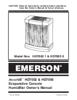
HD7002-1
Brand: Emerson Pages: 16

MA0800
Brand: Emerson Pages: 16

MA1200-1
Brand: Emerson Pages: 19

MJ-E26VX-A1
Brand: Mitsubishi Electric Pages: 28

MJ-E26SX-A1
Brand: Mitsubishi Electric Pages: 24

HE12
Brand: CLEAN COMFORT Pages: 8

Ultra-sorb LH
Brand: DriSteem Pages: 28


