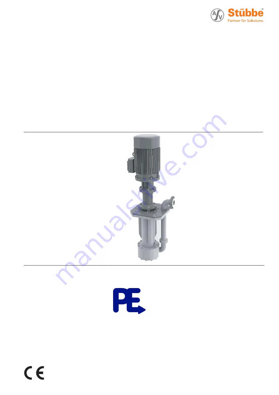
background image

Plastic
Sump Pump

Original Operating Manual

Series ETL

Version

BA-2015.09.17

Print-No.

300 106
TR MA DE Rev002

We reserve the right to make technical changes.
Read carefully before use.
Save for future use.

Distributed in the UK by.....
Pump Engineering Limited.


Unit B1, Riverside Industrial Estate,

Littlehampton, West Sussex, BN17 5DF, United Kingdom
Tel: 01903 730900     Fax: 01903 730234
email:  [email protected]   Web: www.pumpeng.co.uk

Summary of Contents for ETL 20-100

Page 1: ... 0 Fax 49 0 5733 799 5000 Email contact asv stuebbe de Internet www asv stuebbe com We reserve the right to make technical changes Read carefully before use Save for future use Distributed in the UK by Pump Engineering Limited Unit B1 Riverside Industrial Estate Littlehampton West Sussex BN17 5DF United Kingdom Tel 01903 730900 Fax 01903 730234 email sales pumpeng co uk Web www pumpeng co uk ...

Page 2: ... motor 13 5 5 2 Check direction of rotation 13 5 6 Performing the hydrostatic test 13 6 Operation 14 6 1 Preparing for commissioning 14 6 1 1 Checking downtimes 14 6 1 2 Filling and bleeding 14 6 2 Commissioning 14 6 2 1 Switching on 14 6 2 2 Switching off 14 6 3 Shutting down the pump 15 6 4 Restoring the pump to service 16 6 5 Operating the stand by pump 16 7 Maintenance 17 7 1 Inspections 17 7 ...

Page 3: ... pump is shut down 15 Tab 4 Measures depending on the behavior of the pumped liquid 15 Tab 5 Measures to be taken after prolonged shutdown periods 16 Tab 6 Fault number assignment 21 Tab 7 Troubleshooting list 22 Tab 8 Designation of components according to part numbers 23 Tab 9 Ambient conditions 26 Tab 10 Flange tightening torques 26 Tab 11 Sole plate tightening torques 26 Tab 12 Tightening torq...

Page 4: ...bility Read observe and follow this manual and the other applicable documents especially all safety instructions and warnings 1 2 Other applicable documents Document purpose where found Installation drawing Dimensions when installed fitting dimensions etc Documentation included Resistance lists Resistance of materials used to chemicals www asv stuebbe de pdf_resistance 300051 pdf CE declaration of...

Page 5: ... hazardous situation Minor injury Potentially hazardous situation Material damage Safety warning sign Take note of all information highlighted by the safety warning sign and follow the instructions to avoid injury or death Instruction 1 2 Multiple step instructions Precondition Cross reference Information advice Tab 2 Warnings and symbols 300 106 BA 2015 09 17 ETL 5 ...

Page 6: ...s accordingly When conveying fluids containing solids observe the limit values for proportions of solid particles and particle size Data sheet technical description When using auxiliary plant systems Ensure compatibility of the operating medium with the product medium Ensure constant supply of the relevant operating medium Pumps used with water as the pumped liquid must not be used for foodstuffs ...

Page 7: ...charging provide suitable grounding Warranty Obtain the manufacturer s approval prior to carrying out any modifications repairs or alterations during the warranty period Only use genuine parts or parts that have been approved by the manufacturer 2 2 3 Obligations of personnel All directions given on the pump must be followed and kept legible e g the arrow indicating the sense of rotation and the m...

Page 8: ...Shaft seal information 7 Flow 8 Impeller diameter mm 3 2 Description Non self priming vertical centrifugal pump Use in open or closed pressureless containers or pits trenches The pump is dry running safe 3 3 Layout 2 1 3 4 5 6 8 7 9 10 11 12 13 Fig 2 Layout 1 V ring seal 2 Discharge flange 3 Volute casing 4 Strainer optional 5 Suction cup 6 Impeller 7 Protection tube 8 Shaft 9 Immersion tube 10 So...

Page 9: ...ocal regula tions Retain transport frame for horizontal storage recom mended 4 1 2 Lifting DANGER Death or limbs crushed as a result transported items falling over Use lifting gear appropriate for the total weight to be trans ported Attach lifting gear in accordance with the following dia grams Never attach the lifting gear to the lifting eye of the motor other than for securing against knocking o...

Page 10: ...pump twice a month 5 Make sure the shaft and bearing change their rotational position in the process 4 3 Disposal Plastic parts can be contaminated by poisonous or radioac tive pumped liquids to such an extent that cleaning will be insufficient WARNING Risk of poisoning and environmental damage by the pumped liquid or oil Use personal protective equipment when carrying out any work on the pump Pri...

Page 11: ...inimum filling height 5 1 2 Preparing the installation site Ensure the installation site meets the following conditions Pump is freely accessible from all sides Sufficient space for the installation removal of the pipes and for maintenance and repair work especially for the removal and installation of the pump and the motor Pump not exposed to external vibrations damage to bearings Frost protectio...

Page 12: ...charge flanges and non return valve Make provisions for isolating and shutting off the pipes For maintenance and repair work Provide shut off devices in the pressure pipe Allow measurements of the operating conditions 1 Provide pressure gauge in pressure line for pressure mea surement 2 Provide pressure measurement on the pump side 5 4 Connecting the pipes NOTE Material damage due to excessive for...

Page 13: ...otating parts Use personal protective equipment when carrying out any work on the pump Maintain an adequate distance from rotating parts 1 Switch on motor for max of 2 seconds and switch off again immediately 2 Check whether the sense of rotation of the motor matches the direction of rotation on the fan 3 If the sense of rotation is different Change over the two phases 5 6 Performing the hydrostat...

Page 14: ...ork on the running pump Allow the pump to cool down completely before starting any work DANGER Risk of injury and poisoning due to pumped liquid spray ing out Use personal protective equipment when carrying out any work on the pump NOTE Risk of cavitation if suction flow is restricted Open the suction side fitting and do not use to regulate the flow Do not open the pressure side fitting beyond the...

Page 15: ...ver the pump is shut down Pump is Action shut down Take measures appropriate for the fluid Table 4 Measures depending on the behavior of the pumped liquid Page 15 emptied Close suction and pressure side fitting dismounted Isolate the motor from its power supply and secure it against unauthorized switch on put into storage Note measures for storage Tab 3 Measures to be taken if the pump is shut dow...

Page 16: ...ing rings Tab 5 Measures to be taken after prolonged shutdown periods 2 Complete all steps as for commissioning 6 2 Commissioning Page 14 6 5 Operating the stand by pump Stand by pump filled and bled Operate the stand by pump at least once a week Open pressure side fitting far enough so that the stand by pump operating temperature is achieved and heating is even 6 2 1 Switching on Page 14 16 ETL B...

Page 17: ... bearings are subject to natural wear and tear which is heavily dependent on the respective operating condi tions It is therefore not possible to make general state ments about the operating life DANGER Risk of injury from running pump Do not touch the running pump Do not carry out any work on the running pump Before all installation and maintenance work discon nect the motor from the mains and se...

Page 18: ...ts can be very sharp edged due to wear or damage Remove spring loaded components carefully e g mechanical seal tensioned bearing valves etc as com ponents can be ejected by the spring tension Observe the manufacturer s specifications e g for the motor coupling mechanical seal blocking pressure sys tem cardan shaft drives belt drive etc NOTE Material damage due to incorrect dismounting installation...

Page 19: ...aft sleeve 523 1 from the shaft 4 Screw out socket head cap screws 914 4 5 Remove bearing cover 360 2 6 Bend the stem of the securing plate 931 1 to one side and undo the shaft nut 921 1 7 Press the shaft assembly group 211 including distance sleeve 525 and the shaft bearing 321 1 out of the bear ing support towards the hydraulics side 8 Screw out headless setscrews 904 1 9 Remove the sleeve 525 f...

Page 20: ...he pump Only specialist mechanics should complete dismounting installation work NOTE Material damage due to unsuitable components Always replace lost or damaged screws with screws of the same strength where required Only replace seals with seals of the same material NOTE Material damage fragile components Install ceramic parts of the plain bearing and magnets of the magnetic coupling with care do ...

Page 21: ...pressure of system is too high pump selected is too small Consult with the manufacturer X X X Suction head too large NPSHpump is larger than NPSHsystem Increase pump inlet pressure Consult with the manufacturer X X intake suction pipe and pump not correctly vented or not completely filled Completely fill and vent pump and or pipe X X X X Air is sucked in Check filling level of container X X X X Pr...

Page 22: ...r down Consult the manufacturer and adjust the impeller diameter X X X X Motor speed too high Compare the required motor speed with the specifications on the pump type plate Replace the motor if necessary Reduce the motor speed if speed control is available X X X X Impeller diameter too large Throttle down the flow rate at the pressure side fitting Observe the minimum flow rate Machine the impelle...

Page 23: ...550 Disc 554 x Disc 555 Centrifugal disk 556 Round head grooved pin 636 Grease nipple 681 1 Coupling guard 681 2 Contact guard 710 Suction extension 713 Sole plate with support tube 714 Shaft protection tube 716 Pressure connection 801 Motor 840 1 2 Coupling 860 Intermediate ring 893 2 Reinforcement plate 901 x Hexagon head bolt Part no Designation 902 1 Stud bolt 904 1 Headless setscrew 914 4 Cyl...

Page 24: ...Appendix 9 1 2 Drawing ETL 20 100 to 65 200 A B Fig 3 Replacement parts ETL 20 100 to 65 200 A Size 132 B Suction basket optional 24 ETL BA 2015 09 17 300 106 ...

Page 25: ...Appendix 9 1 3 Drawing ETL 80 200 Fig 4 Replacement parts ETL 80 200 300 106 BA 2015 09 17 ETL 25 ...

Page 26: ...avitation Motor IEC standard motor Tolerance 3 dB 9 2 3 Flange tightening torques DN mm Md Nm DN mm Md Nm 15 15 80 40 20 15 100 45 25 15 125 50 32 25 150 65 40 35 200 75 50 40 250 100 65 40 300 110 Tab 10 Flange tightening torques 9 2 4 Sole plate tightening torques Screw Md Nm Screw Md Nm M8 7 M16 63 M10 14 M20 113 M12 24 M24 193 Tab 11 Sole plate tightening torques 9 2 5 Tightening torques of ca...

Page 27: ... 125 35 50 200 80 160 170 125 35 65 200 80 160 170 150 35 80 200 80 180 170 170 35 Tab 13 Installation dimensions minimum dimensions 9 3 Maintenance plan Designation Interval Maintenance Operating temperatures Weekly Check storage temperature Check motor temperature Undoable screwed connections Weekly Check for correct and tight fitting Shaft bearing only for drive capacity 30 kW Monthly Re grease...

Page 28: ... Lubricating points 9 4 2 Lubricant Manufacturer Type of lubricant temperature range 35 C 140 C Aral Aralub HL3 BP Energrease LS3 Glissando Glissando FT3 Glissando 30 Esso Beacon 3 Mobilux Mobilux EP3 Shell Alvania R3 Tab 15 Lubricant Size Quantity g 40 200 5 5 Tab 16 Lubricant quantities 28 ETL BA 2015 09 17 300 106 ...

Page 29: ...is declaration relates are in conformity with the following standards Machinery Directive 2006 42 EC EMV Directive 2004 108 EC With regard to electrical risks the protection objectives of the Low Voltage Directive 2006 95 EC have been complied with in accordance with appendix I no 1 5 1 of the Machinery Directive 2006 42 EC Place and date ____________________ Vlotho 19 08 2013 Name and signature o...

Page 30: ...Appendix 30 ETL BA 2015 09 17 300 106 ...

Page 31: ...Appendix 300 106 BA 2015 09 17 ETL 31 ...

Page 32: ...Appendix 32 ETL BA 2015 09 17 300 106 ...

Reviews: