background image

Consolidated
Operating
Room
Equipment

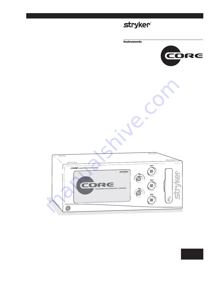
Powered Instrument Driver

REF 5400-50

 5400-050-799 Rev-

5/05

6.x

Software Version

IMPORTANT INFORMATION:

File in your maintenance records

Instructions For Use

••••••••••••••••••••••

US Patents: 6,017,354; 5,689,159; 5,543,695; 6,329,778;
6,045,564; 6,752,816 and other patents pending.

Instruments Division

4100 E. Milham
Kalamazoo, Michigan
(USA) 49001
1-269-323-7700
1-800-253-3210

Summary of Contents for Core 5400-50

Page 1: ... 5 05 6 x Software Version IMPORTANT INFORMATION File in your maintenance records Instructions For Use US Patents 6 017 354 5 689 159 5 543 695 6 329 778 6 045 564 6 752 816 and other patents pending Instruments Division 4100 E Milham Kalamazoo Michigan USA 49001 1 269 323 7700 1 800 253 3210 ...

Page 2: ...ions Standard andAdvance User Mode 26 ToAdjust Audio Video Controls Standard Mode 26 ToAccess Advance User Mode 27 To Return to Standard User Mode 27 To Select Console Language Preference Advance User Mode Only 28 To SelectAdvance Console Settings Advance User Mode Only 28 To Select Network Connections Advance User Mode Only 29 To Set Console Time and Date Advance User Mode Only 29 To Manage User ...

Page 3: ...5 Figure 18 Select User Preference Favorite File 25 Figure 19 Adjust Irrigation Pump Settings Screen 26 Figure 20 Adjust Console Options Screen Standard User Mode 26 Figure 21 Access Advance User Mode Pop up 27 Figure 22 Adjust Console Options Screen Advanced User Mode 27 Figure 23 Return to Standard User Mode Pop up 27 Figure 24 Select Language Preference Screen Advance User Mode 28 Figure 25 Sel...

Page 4: ...cations Commission FCC FCC ID Q9R 5400 This device complies with Part 15 of the FCC rules Operation is subject to the following two conditions 1 this device may not cause harmful interference and 2 this device must accept any interference received including interference that may cause undesired operation NOTE FCC regulations provide that changes or modifications not expressly approved by Stryker I...

Page 5: ...ase read this manual and follow its instructions carefully The words WARNING CAUTION and NOTE carry special meanings and should be carefully reviewed WARNING The personal safety of the patient and user may be involved Disregarding this information could result in injury to the patient and or user CAUTION These instructions point out special service procedures or precautions that must be followed t...

Page 6: ...ccessory combination with a handpiece Contact your Stryker sales representative for a complete list of accessories Failure to comply may result in patient and or operating room staff injury DO NOT attempt to insert or remove any cutting accessory or attachment while the handpiece is operating Failure to comply may result in operating room staff injury DO NOT modify the ground connection of the con...

Page 7: ...ole will only display those options that are related to the connected handpiece An integral irrigation pump system reliably supplies coolant irrigation to the cutting site with adjustable flow rates Various cutting accessories and irrigation cassettes used with the system are also recognized and identified on the console screen by means of a wireless tag technology Console settings like display br...

Page 8: ...ake handpiece settings using its touch screen capability Footswitch Connection Area Allows you to connect two footswitches simultaneously Power Switch Press to turn console power ON and OFF Handpiece Connection Area Allows you to connect three handpieces simultaneously Irrigation Pump Cassette Install the irrigation cassette here if you use the irrigation pump optional Speaker Provides audible sou...

Page 9: ...ed instructions on the next page See the instructions for use supplied with each component for specific connection information The illustrated hardware below provides a likeness but may not be an exact representation of the actual hardware Figure 3 Console Interconnect Diagram Symbol Definitions On Off push push Footswitch Handpiece Irrigation Type BF Applied Part SFB Serial Connection ...

Page 10: ...reless footswitch will be overridden and disabled when a wired footswitch is connected and registered to the same color footswitch port 6 Plug the handpiece cord s into the console port s marked with a HANDPIECE PORT symbol Align the marks and gently push the connectors together Three handpieces may be connected to the console and two handpieces may be operated simultaneously NOTE If using a CORE ...

Page 11: ... default mode of handpiece to OSCillate Set default mode of handpiece to rotate in the Forward clockwise direction Set default mode of handpiece to rotate in the Reverse counterclockwise direction Set default mode of handpiece to operate in the low RPM range mode Set default mode of handpiece to operate in the high RPM range mode Adjust handpiece and footswitch options Set the default run mode of ...

Page 12: ...ew user preference folder Open a user preference folder and modify the file s as required Navigate up one directory Access the Add Handpiece screen Add handpiece to a user preference file View and edit the user preference file settings of a selected handpiece Change user preference file settings Save current console settings to the selected file in the user preference favorites list Adjust console...

Page 13: ... LANGUAGE Select specific network connections Set console time and date not available at this time Select English as console screen language Select German as console screen language Select French as console screen language Select Spanish as console screen language Select Italian as console screen language Set console hour Set console minutes Set AM PM or 24 hour format Set current month Set curren...

Page 14: ...g screen will appear To Power Up This screen is momentarily displayed while the console powers up Note the software version is displayed in the lower right corner of the screen Figure 4 Power Up Screen Figure 5 Plug In Handpiece Cable Screen owered Instrument Driver Po P XXXX XXX XXX X X_build_X ...

Page 15: ...cess Advance Console Controls Select Network Connections Set Console Time and Date Select Console Language Preference Software Menu Navigation The software menu map is a visual representation of how the software is structured and is designed to facilitate navigation The map also provides the sequence of screen information provided in this manual top down and left to right The icons used in this ma...

Page 16: ...onsole Operating Area Access key console functions View User Preference File Name View name of file that contains handpiece settings for a specific procedure for example ACL Anterior Cruciate Ligament surgery View Handpiece Name View name of active handpiece Three handpieces may be connected and displayed Two powered handpieces may be operated from the same console simultaneously View Cutting Acce...

Page 17: ... each handpiece until you adjust the speed set point based on the handpiece capability Touch the adjustment buttons or slider bar that becomes visible when touching the speed value to increase or decrease the speed power set point While the handpiece is running the display shows the actual handpiece speed If the handpiece is not running the default or selected speed is displayed Figure 8 Home Scre...

Page 18: ...eases as the setting approaches zero percent Adjust Oscillate Turns Touch the plus and minus buttons to select the number of turns per direction when running a handpiece in the oscillate mode Touch the minus button until the TIME BASED icon is visible to operate in a TIME BASED mode where the number of turns are based on the speed of the handpiece Select Run Mode FIXED handpiece runs at the full s...

Page 19: ... Port High Low Handpiece port Direction REV Op Mode Default Run Mode Var Direction FWD Op Mode Default Run Mode Var Foot Switch Options FORMULA HANDPIECE 3rd Port Pedal A Options FORMULA HANDPIECE 3rd Port Op Mode Op Mode Default Run Mode Var Direction REV Default High Low OSC Assign Specific Option Select a footswitch pad I II or III or pedal A or B and assign a specific option View Handpiece Por...

Page 20: ...rotation CHANGE PORT pressure on the footswitch pad will change the footswitch assignment to another assigned handpiece FLUSH pressure on the pad will turn the irrigation pump on at the flush rate 300 CHANGE ATTACHMENT pressure on the footswitch pad will toggle through the list of attachments that are available for the handpiece Available attachments are handpiece dependent DISABLE will disable th...

Page 21: ...gned to the handpiece port Green Yellow combination indicates both footswitch ports are assigned to the handpiece port Gray indicates no footswitch port is assigned to the handpiece port Filled yellow icon indicates which handpiece will be operated when the associated footswitch is actuated CORE HIGH TORQUE SABER DRILL FORMULA HANDPIECE Assign footswitch to handpiece SABER DRILL Cord Only FORMULA ...

Page 22: ...e handpiece button SPEED INCREMENT INC button actuation will increment the set point speed SPEED DECREMENT DEC button actuation will decrement the set point speed OSC HIGH LOW button actuation will toggle the operating mode of the handpiece HIGH LOW button actuation will toggle the operating mode of the handpiece speed FWD REV button actuation will toggle the direction of handpiece rotation JOG bu...

Page 23: ...ones ENT Dr Smith NEURO Dr Jones ARTHROSCOPY Default Default To Replace a User Preference Favorite Touch to select one of the five favorite user preference files From the Select a User Preference Favorite pop up touch any of the five User Preference Favorite buttons to make the Swap button active Once active touch the Swap button to select a new favorite preference file NOTE To create or modify a ...

Page 24: ...ders Select a folder and touch the Open Folder button to access the files Figure 17 Select User Preference Favorite Folder Figure 18 Select User Preference Favorite File Touch arrow buttons to scroll through and view the available files Touch the Navigate Up button to return to folder directory Touch to select the desired folder Touch to select the desired file Touch OK button to replace one of th...

Page 25: ...and a minimum pressure of 30 psi when the tubing is blocked AUTO PRIME Tubing Set Touch to activate the priming sequence of the installed irrigation cassette The tubing will be primed from the pump head to the irrigation tip Select Handpiece Touch one or all of the handpiece buttons to allow activation of the irrigation pump If no buttons are selected the pump will not operate Activation will appl...

Page 26: ...ur request Once confirmed the Manage User Preference button will become active To Access Advance User Mode To exit the ADVance user mode touch the ADV button again Touch the OK button if you want to return to the standard user mode To Return to Standard User Mode Adjust console options Access standard mode Return to standard mode Adjust console options 23 23 23 To Adjust the Console Options Standa...

Page 27: ... Mode Touch the button to select the console language preference Touch the arrow buttons to scroll through the list of languages English German French Spanish and Italian Touch the button to select the appropriate console language To Select Advance Console Settings Advance User Mode Only Figure 25 Select Advance Console Settings Screen Advance User Mode Touch the button to select the console advan...

Page 28: ...dvance User Mode Touch the button to toggle network control ON and OFF Touch the button to assign a wireless device to a specific footswitch port To Set Console Time and Date Advance User Mode Only this function not available at this time Figure 27 Set Console Time and Date Screen Advance User Mode Touch the appropriate button to set the hour and minute Touch Mode button to set AM PM or 24 hour fo...

Page 29: ...h navigation Create New Folder Touch to create a new folder Open and Modify Folder Touch arrow buttons to scroll through and view the folders Touch a folder and the Open Folder button to open and modify file s as required Manage user preferences Current f1 t2 file1 Main file file2 To Manage User Preference Files Advance User Mode Only Create New File Touch to create a new file Open View and Edit F...

Page 30: ...a keyboard screen Enter a Folder or File Name Touch key buttons to enter a folder or file name Enter user preference folder Q W E R T Y U I O P Z X C V B N M A S D F G H J K L ENTER SPACE SHIFT XYZ 1 2 3 4 5 6 7 8 9 0 SHIFT Lock Unlock Touch to toggle between upper and lower characters BACKSPACE Touch to delete keystrokes To Manage User Preference Folders and Files Advance User Mode Only Figure 30...

Page 31: ...ettings CORE MICRO DRILL CORE OSC SAW CORE RECIP SAW CORE SABER DRILL CORE SAGITTAL SAW CORE U DRILL CORE U DRIVER Add a handpiece file2 From the Modify File screen touch the Add Handpiece button to add a handpiece to the preference file from a list of available handpieces To Add a Handpiece View and Add a Handpiece Touch arrow buttons to scroll through and highlight a handpiece Touch the ADD butt...

Page 32: ...ce Favorites list and select the file You must also be in the Advanced User Mode For specific screen information see the relevant sections of To Manage User Preference Files Advanced User Mode Only and Replace and Select a User Preference Favorites To Edit Settings Radio Frequency Identification RFID Handpiece and Cutters 1 Once you have selected the file to be edited in the User Preference Favori...

Page 33: ...screen buttons and their function Figure 36 Typical Help Screen View Help Topics Touch the arrow buttons or slider to scroll through and view help topics related to button functions on a specific screen Help Topics Touch the slider bar or the plus minus buttons to adjust the handpiece speed or power set point in rpms or percentage of power 0 to 100 Touch to adjust the handpiece cutting accessory d...

Page 34: ...e longevity performance and safety of this equipment package in original package materials when storing or transporting Cleaning and Sterilization Recommendations WARNINGS Clean and sterilize handpieces and handpiece cables before first and every use Cutting accessories are single use only Sterile only if package is unopened and undamaged DO NOT resterilize or reuse Console Power Cord Cable s and ...

Page 35: ... range and may result in injury Handpiece temperature has exceeded its operating range Allow to cool before restarting Wireless Footswitch Override wireless green yellow footswitch Power supply temperature has exceeded its nominal operating range Performance may be affected Power supply temperature has exceeded its operating range Allow to cool before restarting Console hardware fault detected Han...

Page 36: ...rt Input voltage 100 120 V 50 60 Hz 6 0 A 230 V 50 Hz 3 0 A IPXO Ordinary Equipment Continuous operation with intermittent loading See cycle times defined in handpiece instructions for use Wide 65 minimum viewing angle 6 5 inch diagonal active LCD resolution 800 horizontal x 480 vertical 16 9 aspect ratio 16 bit color dimensions 3 19 in 81 0 mm height 5 67 in 144 0 mm width 0 dBA to 81 dBA CSA Int...

Page 37: ...4100 E Milham Kalamazoo Michigan USA 49001 1 269 323 7700 1 800 253 3210 ...

Reviews: