background image

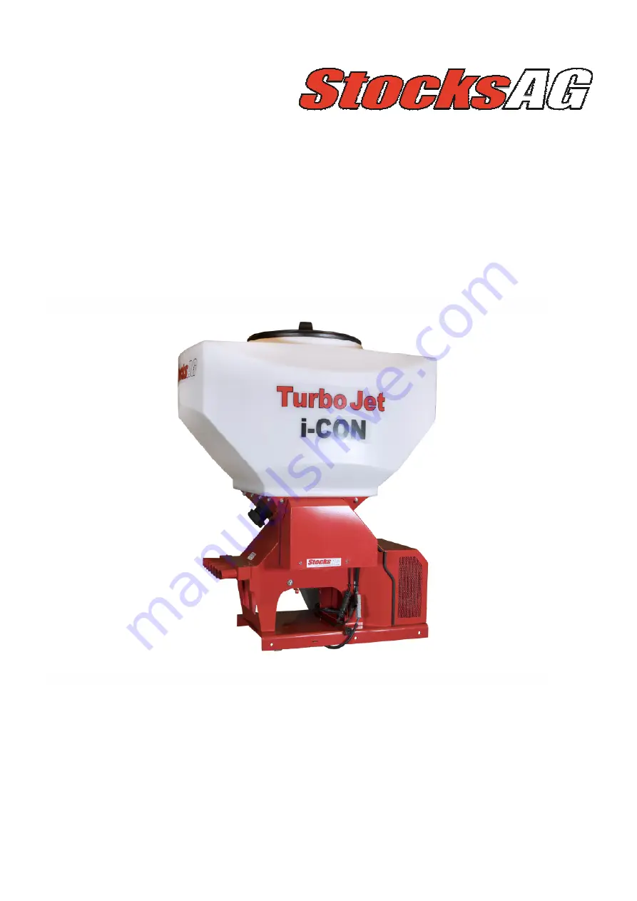
Turbo Jet 8 & 10 i-CON 

Original Operating Manual  

and Parts List 

Read carefully before installation                            

and operation  

This document must not be copied duplicated or distributed without prior consent .                    

All and patent rights apply  

STOCKS AG LIMITED, CROMWELL ROAD, WISBECH, CAMBRIDGESHIRE, UK.  

Tel: 00 44 (0) 1945 464 909  Fax: 00 44 (0) 1945 464985  www.stocks-ag.co.uk 

Original Instructions, Revision 1 August 2020

Summary of Contents for Turbo Jet 10 i-CON

Page 1: ...n and operation This document must not be copied duplicated or distributed without prior consent All and patent rights apply STOCKS AG LIMITED CROMWELL ROAD WISBECH CAMBRIDGESHIRE UK Tel 00 44 0 1945 464 909 Fax 00 44 0 1945 464985 www stocks ag co uk Original Instructions Revision 1 August 2020 ...

Page 2: ...1 Installation guide Page 1 of 2 12 12 2 Base plate 12 13 Installation guide Page 2 of 2 13 14 Machine components Page 1 of 2 14 15 Machine components Page 2 of 2 15 16 1 i CON Control system 16 16 2 Wiring diagram 16 17 1 i CON Instrument functions 17 17 2 Precision farming software access OPTIONAL 17 18 OPTIONAL Feed block setup 18 19 1 OPTIONAL Feed block assemblies 19 19 2 Hopper baffle plate ...

Page 3: ...ce with the conditions for operation maintenance and repairs The implement may only be used maintained and repaired by persons who have relevant experience and aware of the risks involved The manufacturer is not liable for any resulting damage if the machine is used for any other purpose than the intended use also includes compliance with the conditions for operation maintenance and repairs prescr...

Page 4: ...ingdom by Statutory Instrument 2008 No 1597 The Supply of Machinery Safety Regulations 2008 as amended The following standards have been applied in the design and construction of this machine BS EN ISO 12100 2010 Safety of machinery Basic concepts general principles for design Basic terminology methodology BS EN ISO 4254 1 2015 Agricultural machinery Safety General requirements BS EN ISO 4254 8 20...

Page 5: ...normal or excessive wear Warranty expires if damage is caused by external forces operator error modifications Jet washed or if the machine has not been used for its intended use Contact the company whom you purchased the machine from in the event of any problems or before attempting any repair If the base machine or the controls system are modified in any way this will void any warranty claim Plea...

Page 6: ...e ensure that any unused product is returned safely to its original packaging Stocks AG Ltd does not accept any liability for the storage and use of the material being applied If unsure contact the material supplier for more information WARNING Always adhere to the warning information and do not remove any guard whilst the machine is in operation WARNING Do not put your hands inside the hopper whe...

Page 7: ...structions before operating this machine Operator errors can result in serious injury WARNING Do Not Jet Wash This machine is not designed to withstand Jet Washing WARNING Danger moving parts Risk of serious injury whilst the machine is in operation WARNING Risk of injury Keep a safe distance whilst the machine is in operation ...

Page 8: ...it the PVC waterproof cover if available Ensure feed blocks are free to turn and all electrical cables checked following periods of storage 8 3 Optional PVC waterproof covers Heavy Duty White PVC covers available for both the 240L and 400L machines Fitted with eyelets and bungie cord for easy attachment Please contact your locals Stocks AG dealer for more information 8 4 Disposal Ensure that any p...

Page 9: ...product that could contaminate the machine or the environment ensuring any product removed from the machine is put back into its original container Before use 1 Ensure the machine is securely mounted 2 Check the power supply and ensure the power cable is connected direct to the vehicle battery 3 Check the feed block is configured correctly and free running before starting work Daily checks 1 Check...

Page 10: ...event spillage release the two over centre catches and drop the hinged panel under the feed rolls and position the plastic collection tray directly underneath to catch any remaining seed or product 2 Undo and remove the 2 black plastic knobs holding the mechanism in place and slide out the feed block assembly Be aware that the feed block assembly may retain some seed product 3 Use an air line and ...

Page 11: ...e the feed block and check the air chamber below the feed block opening and clear any debris Re position the feed hoses if this has been the cause of the problem See page 12 for advice on best hose positioning 11 3 Checking the feed motor If the control system has alarmed to indicate the feed motor has stalled WARNING this procedure must be carried out by a competent person who is aware of any ris...

Page 12: ...block the air intakes to the fans under the base plate Ensure the hopper does not foul wing sections when folded and the tubes are long enough to fold with the implement without a restriction when in work Ensure you can access the hopper to fill and are able to remove the feed block assembly and position the calibration tray underneath to calibrate or empty Ensure there is room to undo the fan hou...

Page 13: ... bends and uphill runs C Section Rail The spreader plates themselves are mounted to the C section rails 4 x 2m lengths per machine are supplied These can be cut down to suit the implement width The C section rails can be attached to the implement using the supplied straight brackets two per rail which can be welded or bolted into position The spreader plates slide along the rails to give the plann...

Page 14: ...r this switch is when the spring is at rest the feed motor will run normally If required the switch can work in the opposite mode by changing the position of the 2 wires inside the switch so that the switch is out of work when the sprung is at rest To change over remove the PVC cover plate held in position with the retaining screw to access the wiring terminals Remove the 2 wires from terminals 13...

Page 15: ...slug pellets Typically 1 Yellow feed roller would be required per outlet when applying small seed and 1 or 2 White feed rollers when applying slug pellets depending upon the seed or product rate of application working width and forward speed Up to 3 feed rollers per outlet can be fitted if required for other applications Blanking spacers are also supplied in the kit to allow up to 3 outlets to be ...

Page 16: ... following components need to be installed during fitment packed in hopper from factory i Con Instrument TJ117C Instrument cables TJ118C and TJ242A Power supply cables TJ238 and TJ247 GPS Receiver TJ255B Cut out Switch TJ252 i Con Instrument TJ117C Junction Box 6m Instrument Cable TJ242A 5m Power Extension Cable TJ247 12v Fan Agitator Motor Feed Motor Hopper Level Sensor Instrument Connector Cable...

Page 17: ...ct your local Stocks dealer for more details Seed Application Rate kg ha or Seeds m2 Forward Speed km hr Minimum Maximum Forward Speed indicator with alarms beyond which the programmed seed rate cannot be maintained Metering Unit Status On Off and Alarm Fan or Spinner depending on installation Status On Off and Alarm Hopper contents kg and Low Level Alarm Part and Full Job Totals for Area ha Produ...

Page 18: ...rs need to be fitted see page 26 showing all feed roller configurations Changing the feed rollers The feed rollers are easily exchanged by removing the feed mechanism as follows 1 Ensure the hopper is completely empty 2 Undo and remove the 2 black plastic knobs holding the mechanism in place and slide out the feed block 3 Undo and remove the 4 socket head screws on the end of the housing and remov...

Page 19: ...k used under licence by Gowan Crop Protection Ltd Optional feed block assembly for fertiliser application For applying low rates of starter fertiliser or low rates of prilled fertiliser the special Norwood feed block assembly must be fitted Part Number TJ196B for an 8 outlet machine Part Number TJ196F for a 10 outlet machine In addition a stainless feed roller kit will also need to be fitted as th...

Page 20: ...ight delivered whilst calibrating If however as a result of the calibration routine you find that you cannot achieve your desired field speed displayed in the top right corner of the screen then re configure the feed roll assembly and repeat the calibration procedure 8 Prime the feed rolls with product by pressing and holding briefly the prime button on the junction box this will ensure a higher i...

Page 21: ...in Kgs Ha and you will have to reconfigure the display if you want to display Seeds per Square Metre You do not need to enter or change the TGW if working in Kgs Ha only if working in Seeds per Square Metre Refer to the RDS manual Section 3 page 21 Units and TGW Ensure you check the minimum and maximum speeds displayed and that they are sensible for your field operation This is the speed range tha...

Page 22: ...22 22 Parts drawing 5 ...

Page 23: ...ing Shaft 10 outlet 1 11 TJ033 Gasket 1 TJ124C Double Fan Unit 8 10 outlet i CON 1 13 TJ126A Hopper 240L 1 TJ125A Hopper 400L 1 14 TJ138 Agitator Shaft 8 outlet 1 TJ138A Agitator Shaft 10 outlet 1 15 16 TJ219 1 Blanking Plug 8 10 outlet 3 17 TJ218A Feed Unit Manifold 8 outlet 1 TJ217A Feed Unit Manifold 10 outlet 1 18 19 TJ220 Ass Y Connector Assembly 8 per TJ8 or 10 per TJ10 20 TJ222 Feed Hose 30...

Page 24: ...5 M5 011 M5 Setscrew 4 56 M5 014 M5 Flat Washer 4 57 M6 004 M6x16 Bolt 2 58 M6 004 M6x16 Bolt 3 59 M6 007 M6x20 CSK Setscrew 4 60 M6 016 M6 Flat Washer 6 61 M6 008 M6x25 Button Head Setscrew 4 62 M8 004 M8x20 Dome SQ Bolt 16 63 M8 010 M8 Flat Washer 16 64 M8 012 M8 Penny Washer 2 65 M10 001 M10x16 Bolt a r 66 M4 004 M4 Lock Nut 4 67 M10 016 M10 Flat Washer a r 68 M10 024 M10 Lock Nut 3 69 M12 003 ...

Page 25: ...03 TJ118C i CON Instrument Connector Cable 1 Not shown 104 TJ119D i CON Junction Box 1 105 TJ233A Ground Speed Radar Cost Option 106 TJ231 Radar Bracket Cost Option 107 TJ252 Finger Cut Out Switch 1 108 TJ254 6m Switch Cable 1 Not shown 109 110 TJ237 Radar Bracket Assembly Cost Option 111 TJ238 5m Fused 40A Power Cable 1 112 TJ242A 6m i CON Instrument Ext Cable 1 113 TJ247 5m Power Extension Cable...

Page 26: ...26 26 Feed roller kits ...

Page 27: ... Roller Kit consisting of the following 10 TJ207A 3mm Spacer 2 11 TJ208 10mm Spacer 1 12 TJ212 12 25mm Spacer 2 13 GA110 20 Section Feed Rollers 4 TJ193A 8 Outlet Grass Seed Roller Kit consisting of the following 16 TJ207A 3mm Spacer 2 17 TJ212 13 5mm Spacer 2 18 TJ208 10mm Spacer 1 19 GA110B A 8 Section Grass Seed Roller A 4 20 GA110B B 8 Section Grass Seed Roller B 4 TJ192A 8 Outlet 1 2 Grass Se...

Page 28: ...Outlet 20 Section Seed Rolls Kit consisting of the following 38 TJ207A 3mm Spacer 1 39 GA110 20 Section Seed Roll 5 TJ197D 10 Outlet Grass Seed Rolls Kit consisting of the following 43 TJ211 6 5mm Spacer 2 44 TJ214 5 3mm Spacer 9 45 GA110B A 8 Section Grass Seed Roller 5 46 GA110B B 8 Section Grass Seed Roller 5 TJ197E 10 Outlet 1 2 Grass Seed Roller Kit consisting of the following 50 TJ209 15 4mm...

Page 29: ...29 29 Notes page ...

Page 30: ...30 ...

Reviews: