SteppIR WIRELESS, Setup Instructions
Introducing Targus WIRELESS - a cutting-edge gadget designed to provide seamless connectivity. Unlock the full potential of this device by following the comprehensive User Manual available for free download at manualshive.com. Delve into the intricacies of this product, as this manual offers step-by-step instructions and troubleshooting tips for an optimal user experience.
Share
Download


Reviews:
No comments
Related manuals for WIRELESS

CX-20
Brand: Barco Pages: 4

C5011S
Brand: Barco Pages: 158

Himax X-COM 01
Brand: HIMA Pages: 42

001G4040EZT
Brand: CAME Pages: 128

FUTURA F-5593
Brand: The Fisher Pages: 20

2500-12SPRVSR
Brand: Rath Pages: 7
VoiceFriend
Brand: ICON Pages: 6

UPBX 416
Brand: Uniden Pages: 36
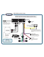
MP5720USB
Brand: Jensen Pages: 3

AIR ADJUST 2940
Brand: Yetter Pages: 64

GGT40ACS
Brand: CAME Pages: 40

A2D-TOY03
Brand: Discount Car Stereo Pages: 5

Sound Pad S1
Brand: Hengbida Electronic Technology Pages: 19

SWACE
Brand: Suzuki Pages: 150

AT-50B
Brand: Mitsubishi Electric Pages: 68

AJ65VBTCU-68DAVN
Brand: Mitsubishi Electric Pages: 112

BAC-HD150
Brand: Mitsubishi Electric Pages: 48

AT-50B
Brand: Mitsubishi Electric Pages: 20


