STEELE PRODUCTS SP-GG350, Owner'S Manual
The STEELE PRODUCTS SP-GG350 is a powerful and reliable generator that provides efficient energy backup. Ensure optimal performance by referring to the comprehensive Owner's Manual available for free download at manualshive.com. This essential manual provides step-by-step instructions and troubleshooting tips to maximize your experience with this exceptional product.
Share
Download


Reviews:
No comments
Related manuals for SP-GG350
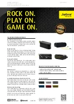
SOLEMATE MAX
Brand: Jabra Pages: 2

BLAST
Brand: Ultimate Ears Pages: 2

HG50.25.V2
Brand: Sealey Pages: 5

73531i
Brand: Champion Pages: 34

PR-D4W
Brand: Sangean Pages: 22

Scout 35
Brand: Tivax Pages: 31

TG32P31
Brand: ETQ Pages: 32

DVD7015R
Brand: Curtis Pages: 29
SRS-RF930RK - Wireless Speaker Sys
Brand: Sony Pages: 2

SA-VE356T
Brand: Sony Pages: 2

XDR-M1
Brand: Sony Pages: 2

FDL-PT222 - Watchman Lcd Color Tv
Brand: Sony Pages: 24

SRS-D313
Brand: Sony Pages: 14

SRS-RF930RK - Wireless Speaker Sys
Brand: Sony Pages: 26

GSS6100
Brand: Spirent Pages: 179

SB2000
Brand: Studebaker Pages: 10

Panda 4800i PMS
Brand: Fischer Panda Pages: 180

Efco DS 3000 D-PU
Brand: EMAK Pages: 164


