Steel City 35903, User Manual
Get your hands on the comprehensive user manual for the high-performance Steel City 35903. Experience seamless functionality and effortless operation with this powerful device. Download the user manual for free from our website and unlock the full potential of your Steel City 35903.
Share
Download


Reviews:
No comments
Related manuals for 35903

31720
Brand: nativa Pages: 36

BTA 90
Brand: ATIKA Pages: 44

190932
Brand: Klutch Pages: 6
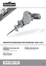
FAAS 12 B1
Brand: FLORABEST Pages: 35

DS-250-N 1000
Brand: Rubi Pages: 28

SH-155
Brand: Sammic Pages: 40

PZKS 2000 A1
Brand: Parkside Pages: 80

92386
Brand: Chicago Electric Pages: 25

2075CR-B
Brand: Bauer Pages: 12

MS250A
Brand: Draper Pages: 24

MS250
Brand: Draper Pages: 24

BTS255
Brand: Draper Pages: 24

LS700
Brand: P.Lindberg Pages: 41

39012299933
Brand: PrimAster Pages: 56

T-SAW180G
Brand: MSW Motor Technics Pages: 19

Pattfield E-HKS 1600-Laser
Brand: Ergo tools Pages: 76

ERB566CSW
Brand: Erbauer Pages: 22

95-211
Brand: ETC Tools Pages: 10


