

Quick-Start Guide
Manual Revision: 11/09/2018
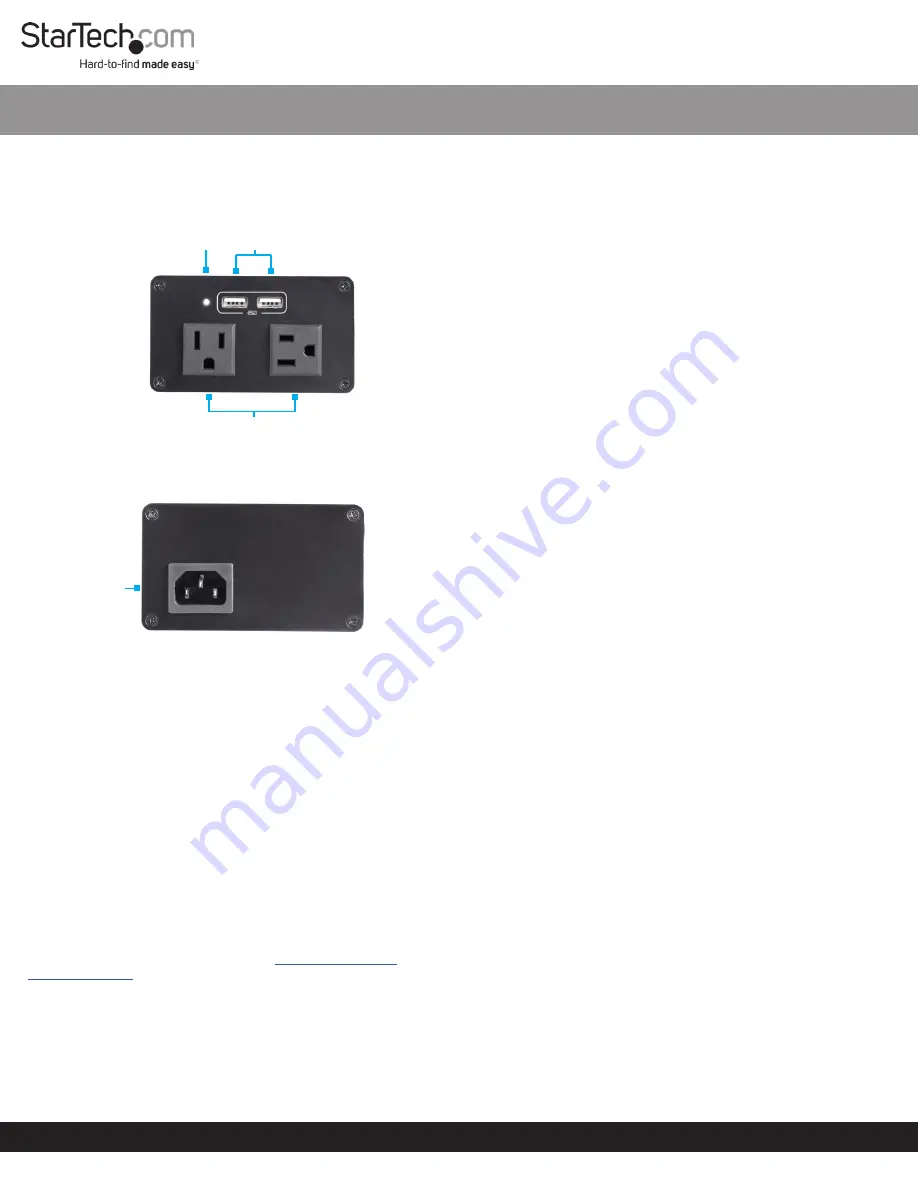
Product Design
Actual product may vary from photos
Front View
Rear View
Package Contents
• Power Module x 1
• Power Cord x 1
• Installation Kit x 1
• Mounting Bracket x 1
• Mounting Bracket Screws (M5 x 20 mm) x 4
• Module Screws (#6-32 x 3/16) x 8
• User Manual x 1
SKU: BNDBXHDBTPNA, BNDBXDOCKPNA, or BNDBXAVHDPNA
• Conference Table Box x 1
• Installation Kit x 1
• Die Cut Outline x 1
• Wing Nut Bracket
Requirements
For the latest requirements, please visit
.
Installation
See the Installation section in the
Modular Table Box
(BOX4MODULE) or
Single-Module Table Box
(BEZ4MOD)
User
Manual
for instructions on how to install a module into a table
surface.
SKU #:
MOD4POWERNA
North American Power Module BOX4MODULE | BEZ4MOD
(Optional) Mounting
Note:
StarTech.com is not responsible for any damages related to
the installation of this product.
Installation Requirements:
• Mounting Bracket x 1
• Bracket Screws (M5 x 20 mm) x 4
• Module Screws (#6-32 x 3/16) x 8
• Writing Utensil x 1
• Phillips Head Screwdriver x 1
Note:
Before mounting the
Module
, take into consideration
the mounting orientation of the
Module
. This will affect the
orientation of the ports (top and bottom).
1. Align the
Mounting Bracket
with the four
Mounting Holes
on
the
Module.
Note:
The
Module
has four
Mounting Holes
on each side,
which gives you two different mounting options.
2. Insert the
Bracket Screws
(x4) through the
Mounting Bracket
and into the
Mounting Holes
.
3. Tighten the
Mounting Screws
using a
Phillips Head
Screwdriver
, be careful not to overtighten.
4. Before installing the
Mounting Bracket
, measure and position
the
Mounting Bracket
in the desired location. The
Module
can
be mounted on a vertical or horizontal surface.
Note:
Depending on the surface you are using to install the
product, you may need to drill pilot holes prior to installing the
screws into the surface.
5. Mark the location of the
Mounting Holes
using a
Writing
Utensil
. These marks can be used as a guide to indicate where
the
Mounting Screws
will be installed in the surface.
6. Install the
Bracket Screws
(x4) through the
Mounting
Bracket
and into the mounting surface, using a
Phillips Head
Screwdriver
. Be careful not to overtighten.
Warning:
To prevent the
Mounting Screws
from penetrating
the opposite side of the installation surface, be conscious of
the size of the
Mounting Screw
compared to the depth of the
surface.
Powering the Module
1. Connect the
Power Cord
to the
C14 Power Receptacle
, on the
bottom of the
Power Module
.
2. Connect the other end of the
Power Cord
to an
AC Electrical
Outlet
.
Connecting a Device to the Module
USB-A Port
The
USB-A Port
will charge up to two
USB Devices
(e.g. Cell
Phone, Laptop, Tablet, etc.).
Note:
The
USB-A Ports
support Smart Charging (Smart IC).
Smart Charging supports a wide variety of charging protocols (e.g.
Battery Charging 1.2, Apple, Samsung™, etc.).
For the latest information, specifications, and support visit www.startech.com/MOD4POWERNA.
USB A
Ports
AC Electrical
Outlets
C14 Power
Receptacle
LED
Indicator


