background image

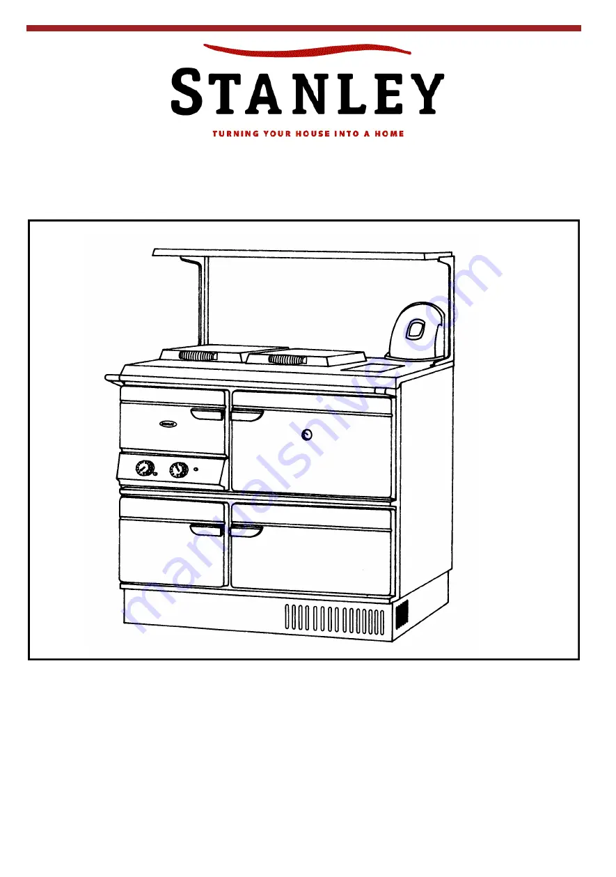
Donard 60 Oil fired Cooker

To ensure safety, satisfaction and reliable service, 

this quality Cooker should be installed by a competent

person. 

The provision of a Central Heating facility, requires that the hot water supply system involved,

conforms fully to good plumbing practice and established standards.

Installation and Operating Instructions

To be left with end user.

(SUPER STAR 60 K OIL FIRED COOKER)

Summary of Contents for Donard 60

Page 1: ...hould be installed by a competent person The provision of a Central Heating facility requires that the hot water supply system involved conforms fully to good plumbing practice and established standards Installation and Operating Instructions To be left with end user SUPER STAR 60 K OIL FIRED COOKER ...

Page 2: ...ts 9 19 Ventilation Combustion Air Requirements 9 20 Outside Air Connection 10 21 Down Draughts 10 22 Factory Made Insulated Chimneys 10 23 Suitable Materials 11 24 Heating 11 25 Safety Valve 11 26 Pipe Fittings 12 27 By Pass Loop 12 28 Airing Cupboard Layout 12 29 Plumbing Diagrams 13 30 Pipe Thermostats 14 31 Water Circuit Temperature 14 32 Indirect Domestic Cylinder 14 33 General Maintenance 14...

Page 3: ...t Plate 18 50 Hotplate Insulating Covers 18 51 Cooking Utensils 19 52 Heating System Controls 19 53 Wiring Diagrams 19 54 Commissioning Checks 21 55 Function 21 56 Servicing 21 57 Flue Cleaning 22 58 Firebox cleaning 22 59 Cleaning 23 60 Mild Steel 23 61 Ovens 23 62 Hot Plate 23 63 Condensation 24 64 General Servicing Cleaning of the Appliance 24 65 Fault Findings 25 ...

Page 4: ...ious to health and safety When handling Firebricks Fire Cement or Fuels use disposable gloves Exercise caution and use disposable masks and gloves when handling glues and sealants When working with fibre glass mineral wool insulation materials ceramic blanket board or kerosene fuel oil avoid inhalation as it may be harmful Avoid contact with skin eyes nose and throat Use disposable protection Inst...

Page 5: ...50mm 6 90o Bend 5 Bend Cleaning Plate 6 Hob 7 Towel Rail 8 Firedoor 9 Burner Door 10 Main Oven Door 11 Simmer Oven Door 12 Base Frame 13 Hotplate 14 Simmer and Cleaning Plate 15 Boiler Thermostat 16 Oven Thermostat 17 Indicator Light 18 Reset Button Hi Limit Stat Fig 1 0411094 ...

Page 6: ...Part 1 Oil Installations under 45kW The Building Regulations Part J England Wales Part F Section 4 Scotland Part L Northern Ireland The Building Regulations Part J Republic of Ireland The Control of Pollution Oil Regulations B S 5449 Forced circulation hot water central heating system for domestic installation Health and Safety at Work Act B S 7671 Requirements for Electrical Regulations Safety Do...

Page 7: ...that all flue joints are tightly sealed against flue gas leakage and tested accordingly See fig 3a 3b INSTALLATION Fig 3 Note Connecting pipe shall be constructed of cast iron complying with BS41 1973 or mild steel not less than 4 75mm thick 150mm 6 150mm 6 Inspection Cover Catchment Space Non combustible material within 30mm of top of flue pipe bend Flexible Liner 150mm 6 Vermiculite filler or co...

Page 8: ...on of the appliance and any system controls to the mains supply must be through a moulded on plug top with a 5 Amp fuse fitted which is fitted to the appliance in accordance with EN 60335 Consumer Protection SI 1994 No 1768 plug and sockets etc safety Regulations 1994 ALWAYS INSTALL IN ACCORDANCE WITH CURRENT LOCAL WIRING REGULATIONS WARNING THIS SUPPLY AND APPLIANCE MUST BE EARTHED Refer to B S 7...

Page 9: ...pipe must terminate at a point not lower than the main ridge or adjacent outside obstructions Where such installations exist access to the chimney must be provided for cleaning purposes Horizontal runs more than 305mm 12 and 90o bends numbering more than 2 per installation should be avoided If it is necessary to offset the chimney the recommended angle is 60o to the horizontal and the statutory mi...

Page 10: ...very flue system be inspected and tested by a competent person for its correct effectiveness to ensure that the combustion products are completely discharged to the outside atmosphere 9 DRAUGHT REQUIREMENTS If connecting to a chimney a steady draught of between 1mm 04 and 1 5mm 06 inches W G is required When a draught recorded is over 1 5mm 06 inches W G a draught stabiliser must be fitted externa...

Page 11: ...s cooker to an outside air supply use 125mm 5 kit to order See fig 8b 5 Air inlets traversing cavity walls should include a continuous duct across the cavity The duct should be installed in such a manner as not to impair the weather resistance of the cavity This duct must also be satisfactorily fire proofed as per Building Regulations 6 Joints between air vents and outside walls should be sealed t...

Page 12: ...patible with the requirements of the cooker d Are any modifications necessary to make the heating system more efficient e Cleanse the system and add suitable inhibitor SAFETY VALVE A non adjustable 3 bar safety valve must be fitted to the primary flow pipe adjacent to boiler connection ensuring that any discharge will not create a hazard to occupants or cause damage to electrical components or pro...

Page 13: ... pass must be fitted not less than 1 5 meters 4 9ft from the cooker to allow correct water circulation for the pump and to prevent condensation forming in the boiler This should be balanced A heat sink radiator must be installed in addition to the By Pass Loop See Fig 11 11A BS 6956 Jointing Materials 1 2 Non Ferrous Materials EN 29453 Soft Solder Alloys BS 864 Compression tube fittings BS 2871 BS...

Page 14: ...sed as working drawings 2 STOREY HOUSE FULLY PUMPED BUNGALOW FULLY PUMPED USING MOTORISED VALVES 2 STOREY HOUSE FULLY PUMPED USING MOTORISED VALVES Fig 12 Fig 13 Fig 14 Fig 15 2 STOREY HOUSE FULLY PUMPED SEALED SYSTEM Fig 16 BUNGALOW FULLY PUMPED SEALED SYSTEM DONARD 60 COOKER DONARD 60 COOKER DONARD 60 COOKER DONARD 60 COOKER DONARD 60 COOKER ...

Page 15: ...uit only See Fig 11A GENERAL MAINTENANCE It is important that the user is familiar with their heating system and that they ensure regular checks and maintenance which can limit unnecessary breakdowns We recommend that you evaluate the overall insulation in your house i e attic external walls window and external doors Insulation and draught proofing can greatly reduce running costs while equally en...

Page 16: ...ittings must not be used Screwed joints must only be made with taper threads complying to B S 1740 Part 1 Jointing materials must be of types intended for use with oil fuel Special petroleum resisting compounds and PTFE tape are suitable External pipes should preferably be run with a continuous rise towards the direction of flow so that air can be vented off It is important to avoid high points wh...

Page 17: ...ection 4 Scotland and Part L Northern Ireland The Building Regulations Part J Rep Ireland Single pipe system with de aeration device fitted This system can be used where the tank base is below the level at which gravity feed to the burner can be maintained and the burner incorporates an oil pump The chamber is fitted close to the burner and is linked to the tank by a Fig 23 single pipe thus saving...

Page 18: ...Plate Output with Boiler and Oven 1 Set the boiler thermostat to idle 2 Turn both boiler baffle control knobs to down position 3 Set the oven thermostat as required to control hot plate temperature Setting C High Oven Output with Hot Plate and Low Boiler Output 1 Set the boiler thermostat to idle 2 Turn the right hand boiler baffle control knob clockwise until it engages 3 Set the oven thermostat ...

Page 19: ...ved Commissioning Service Agent CENTRAL HEATING The boiler output is determined by the position of the boiler baffle as follows Setting A Boiler Max Output 17 6 kW 60 000 BTU s hr Setting B Hotplate Max Output 11 kW 38 000 BTU s hr Min Output 6 kW 20 000 BTU s hr Setting C Oven Max Output 7 kW 25 000 BTU s hr Min Output 2 6 kW 9 000 BTU s hr The above may vary slightly depending on individual inst...

Page 20: ...HICH MAY UNSUITABLE DO NOT USE ROUND BASED WOKS IMPORTANT WE DO NOT RECOMMEND DEEP FAT FRYING ON THIS APPLIANCE HEATING SYSTEM CONTROLS We recommend the use of zone control valves especially in larger systems see plumbing schematics OPENING COOKER DOOR To open the cooker door grip the door handle between the fingers and thumb as per Fig C swing the door handle in an outwards and upwards direction ...

Page 21: ...0 Oil 220 240V A C 50Hz Fig 28 WARNING Before carrying out any servicing or maintenance isolate cooker from mains supply as switching off the time switch will not break constant live circuit WARNING THIS APPLIANCE MUST BE EARTHED ...

Page 22: ...21 S PLAN WIRING DIAGRAM WIRING DIAGRAM Fig 29 Fig 30 OPTIONAL PIPE THERMOSTAT 2 SET AT 85 0 C DONARD 60 OIL COOKER ...

Page 23: ...ion and pre purging pre ignition alone 7 seconds Oil is released and the burner operates if the flame forms within the safety time of 10 seconds Post ignition after oil release BHO 61 5 seconds False light at start If oil is released and no flame is established the control will cut out within the safety time of 10 seconds No flame formation at start If oil is released and no flame is established t...

Page 24: ...roughly clean out the residue from the side flues and base plate through the warming oven cleaning opening 4 Check flue and clean as necessary FIREBOX CLEANING 1 SWITCH OFF ELECTRICAL AND OIL SUPPLY TO THE COOKER Fig 33 2 To remove the burner take out the four screws from the base frame which will drop the air grill and cover plate Remove the four outer screws from the cover plate of the front of ...

Page 25: ...e cooker be sure to wipe it immediately or the vitreous enamel may be permanently discoloured Jam and preservatives containing sugar can permanently damage the vitreous enamel 3 Keep a damp cloth to hand while cooking to wipe up any spills as they occur so they do not harden and become more difficult to remove later 4 If spills do become baked on a cream cleanser can be used For stubborn deposits ...

Page 26: ...roughly clean out the residue from the side flues and base plate through the oven passage cleaning door located at the top of the warming oven 12 Remove cover over blast tube in fire box 13 Vacuum out the fire box area 14 When cleaning this appliance be careful not to damage ceramic baffles 15 Re assemble the cooker and carry out each commissioning check as specified 16 When replacing the cleaning...

Page 27: ... a Set baffle knobs b Circulating pump not working b Check and replace if defective c Pipe thermostat set too high c Reduce thermostat settings d Air in system d Bleed system e Pipe system faulty e Check pipe sizes and circuit f Excessive number of radiators f Turn off un needed radiators g Radiator valves not balanced g Adjust valves to give an even flow 8 Domestic Hot Water a Cylinder too large ...

Reviews: