

Step 1
Mount the radar. See provided
Quickstart Guide
SP-Mount-1 or SP-Mount-RINO
for details on mounting
and install practices. Be aware some models require
specific orientation for installation as indicated by
orientation stickers.
Step 3b
GTC Connector instructions Once the
cable has been tested and is ready for final installation,
fill Radar GTC connector with dielectric grease. Ensure
each contact/pin is heavily covered. (Fig. 3)
Step 4b
Coat contacts/pins on incoming RJ45 with
dielectric grease and connect RJ45 to GTC connector
on radar. (Fig. 4)
Warning:
Do not apply grease until ready for final
connection. A contaminated connection can cause failure.
DO NOT USE GREASE ON PQT CONNECTIONS!
Fig. 3
WARNING
: ALL CABLES USED MUST BE OUTDOOR RATED, CAT5E, AND SHIELDED
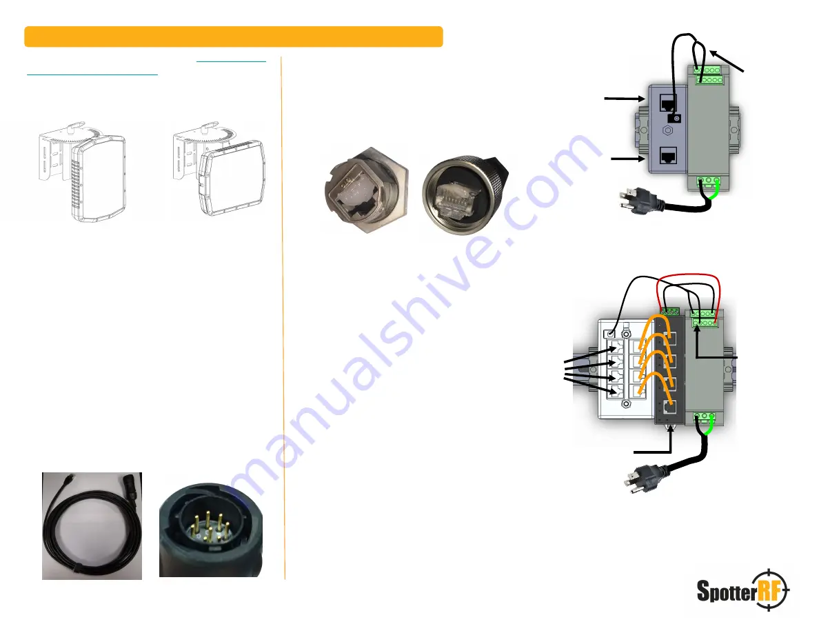
Step 6
Power PoE injector and connect network
to the radar. If using a SpotterRF power kit,
connect to the port labelled “Network” in the
diagrams to the right.
(If using an Integrated
Control Cabinet, see Cabinet quickstart for
Network Port locations.)
Fig. 4
Step 2
Before connecting the Radar to PoE, ensure the
Ethernet Cable being used is tested for continuity to ground,
network connection, and power consumption.
(See Quickstart Guide SP-TESTKIT or Youtube video for
testing instructions, QR Code and Link found on the next
page for tutorial.)
Radar
Network
Network
Radar
Step 7
To access the radar UI, connect a computer
via ethernet to the Network Port. Set your PC to “Obtain
Automatically” IP settings or DHCP.
The UI can be accessed by entering 169.254.254.254
into a web browser. Google Chrome and Firefox are
recommended.
169.254.254.254 is the default IP address for all radars.
When using the default address, ensure that the
computer is set to DHCP and only one radar is
connected. Otherwise, there may be a network conflict
between radars.
Step 5
Connect radar ethernet to PoE. If using a
SpotterRF power kit, see diagrams to the right. Connect
to the port labelled “Radar”.
(If using an Integrated
Control Cabinet, refer to the cabinet quickstart for PoE
port locations.)
Wire without
writing is (+) for
PoE Injector
Wire without
writing is (+)
for PoE Injector
Quickstart Guide - SpotterRF Radar
SP-POWER-1
SP-POWER-4
Fig. 1
Fig. 2
Step 3a
PQT Connector instructions: The PQT is not
field serviceable (Fig. 1). To adjust cable length, do so by
cutting off the RJ45 end to the correct length and recrimping
a new end. RJ45 to RJ45 waterproof coupler supplied to
support longer cable lengths.
Step 4a
Connect to radar by aligning indexing pins
correctly (Fig. 2), push in connector, rotate locking ring
clockwise until seal connection locks.
04/07/20 REV 003
CK2B-CE


