background image

M

ANUAL 

1183437

$18.00

COUNTERTOP STEAMER

MANUAL SECTION ST

OPERATOR’S MANUAL

Super Simple Steam

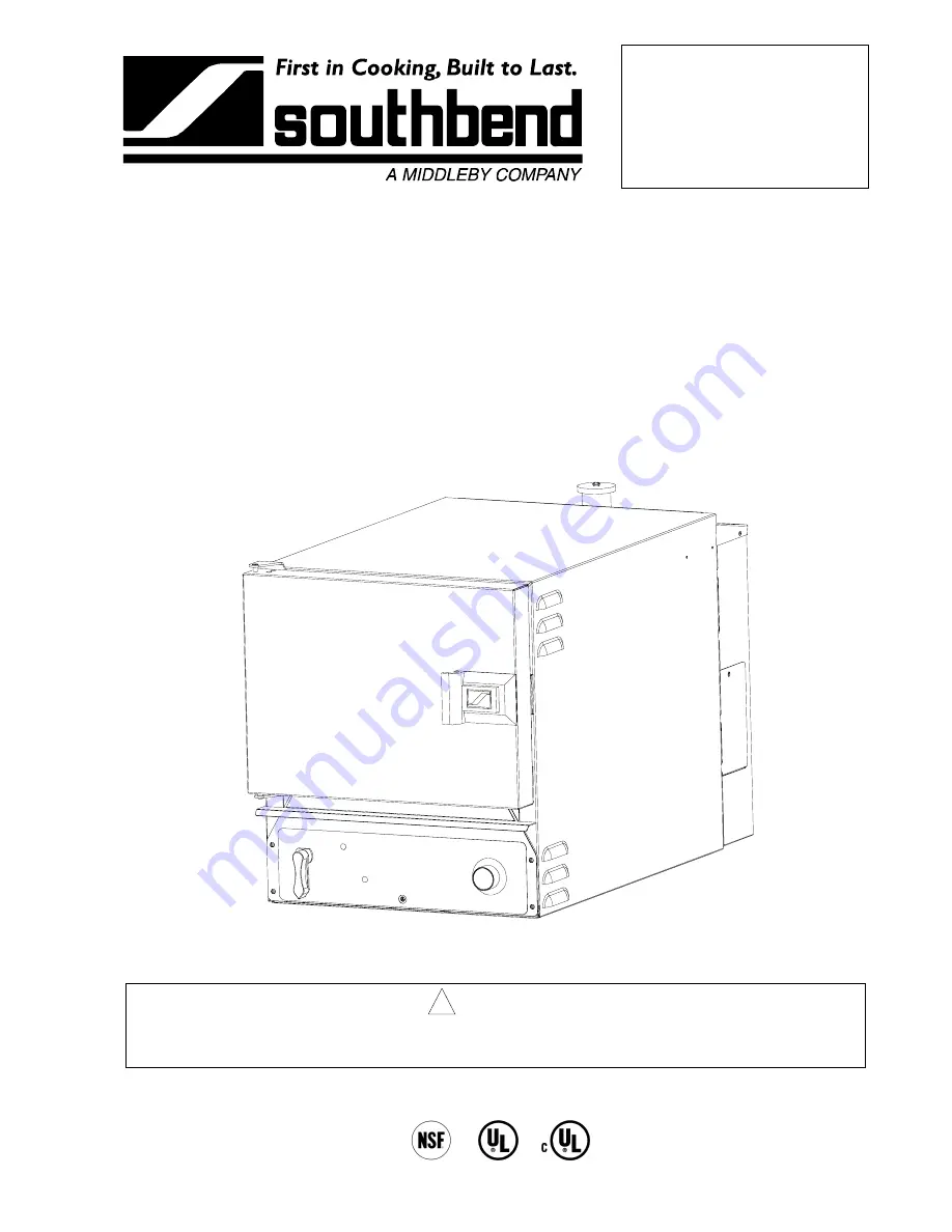
SEZ Series Countertop Steamers

For Models SEZ/3 & SEZ/5 Built After February 15, 2001

Model SEZ/3

!

   WARNING

Improper installation, operation, service, or maintenance can cause property damage, injury, or death.

Read this manual thoroughly before installing and operating this equipment.

1100 Old Honeycutt Road, Fuquay-Varina, NC 27526

(800) 348-2558 or (919) 552-9161 

 FAX (800) 348-2558 or (919) 552-9798

IMPORTANT FOR FUTURE REFERENCE

Please complete this information and retain this
manual for the life of the equipment:

Model #: __________________________
Serial #: __________________________
Date Purchased: ___________________

Summary of Contents for SEZ-3

Page 1: ...ance can cause property damage injury or death Read this manual thoroughly before installing and operating this equipment 1100 Old Honeycutt Road Fuquay Varina NC 27526 800 348 2558 or 919 552 9161 FAX 800 348 2558 or 919 552 9798 IMPORTANT FOR FUTURE REFERENCE Please complete this information and retain this manual for the life of the equipment Model __________________________ Serial ____________...

Page 2: ...th CAUTION This symbol refers to a potential hazard or unsafe practice which could result in injury product damage or property damage NOTICE This symbol refers to information that needs special attention or must be fully understood even though not dangerous WARNING FIRE HAZARD For your safety do not store or use gasoline or other flammable vapors and liquids in the vicinity of this or any other ap...

Page 3: ...ts Specifications 4 Installation 6 Operation 12 Cooking Hints 13 Cleaning 16 Troubleshooting 18 Parts 40 Read these instructions carefully before attempting installation Installation and initial startup should be performed by a qualified installer Unless the installation instructions for this product are followed by a qualified service technician a person experienced in and knowledgeable with the ...

Page 4: ...AR VIEW Water Drain Water Inlet Electrical Connection 2 4 Interior Dimensions Pan Capacity Crate Dimensions Model Overall Height Width Depth Height 1 2 5 4 Width Depth Height Crated Weight SEZ 3 19 0 13 5 22 0 9 5 6 3 2 19 5 31 5 28 5 150 lbs SEZ 5 25 0 13 5 22 0 15 5 9 5 3 19 5 31 5 34 5 175 lbs Pan Capacity is the number of 1 2 5 or 4 high standard pans 12 wide x 20 deep that the steamer will ho...

Page 5: ...nts a water treatment system softener is recommended when water quality does not meet the limits stated above DRAIN REQUIREMENTS The drain outlet has a 3 8 NPT male connector DO NOT directly connect the drain to a plumbing system unless you also install an open funnel downstream of this connection There must be no back flow or back pressure into the drain connection CONSTRUCTION SPECIFICATIONS Ext...

Page 6: ...n Electrical Code Part II 109 M1981 Commercial Cooking Appliances NOTICE EXHAUST FANS AND CANOPIES It is recommended that the steamer be installed under a ventilation hood Consult local codes for proper installation of hoods Proper ventilation is the owner s responsibility Any problem due to improper ventilation will not be covered by warranty LEVELING Unit must be level to assure maximum performa...

Page 7: ... is to be installed on legs locate legs and install as shown in Figure 2 below Figure 2 4 If the unit is to be installed on a counter top or other surface without using legs the unit must be sealed to the surface to prevent any water grease etc from accumulating under the steamer The steamer can be bolted to the counter but will still have to be sealed The installer may use G E or Dow Corning RTV ...

Page 8: ...INSTALLATION SEZ SERIES COUNTERTOP STEAMERS PAGE 8 OPERATOR S MANUAL 1183437 INSTALLATION Figure 3 BOTTOM VIEW Sealant Sealer Steamer ...

Page 9: ...uirement on the serial plate The unit is factory wired per customer order WARNING A POSITIVE GROUND CONNECTION IS ESSENTIAL DO NOT ALLOW ANY TAMPERING OR ADJUSTMENT OF ANY CONTROL OR WIRING THE UNIT IS FACTORY SET ADJUSTING ANY INTERNAL COMPONENT OTHER THAN THE MAIN FUSE BLOCK CAN VOID THE WARRANTY THIS UNIT REQUIRES A KIT TO BE FIELD CONVERTED FROM THREE PHASE TO SINGLE PHASE OR VICE VERSA CONSUL...

Page 10: ...Pressure 30 to 60 PSI Total Dissolved Solids TDS 60 PPM Hardness 2 grains or 35 PPM pH 7 0 to 7 5 Connect a cold water line to the water inlet strainer on the back of the steamer as shown in Figure 4 on page 9 The connector on the unit is 1 4 NPT male NOTE To facilitate cleaning and allow access to rear of unit flexible connections are recommended A shut off valve at or near the rear of the unit i...

Page 11: ...ontal piping between the unit and the air gap above the open funnel The open funnel is intended to eliminate any water from entering the steamer because of a blocked drain and it also prevents any back pressure within the steamer cavity Any connection that allows the build up of back pressure in the unit such as a reduction in pipe size to a line smaller than 3 8 or more than one 90 degree angle i...

Page 12: ... the table in the following section 2 Pan specifications are shown on specifications page page 4 3 The door may be opened or closed at any time 4 Timer can be used as desired but it has no effect on the operation of the unit 5 Unit will automatically idle at operating temperature when and if the door is closed and there is no food in the cavity SHUTDOWN 1 Turn lever to the OFF position 2 Remove pa...

Page 13: ...4 4 oz 20 4 oz 8 10 9 Full Perforated Full Perforated Beans Green Frozen Cut Green Fresh Wax Frozen Lima Frozen 5 lbs 5 lbs 5 lbs 5 lbs 20 4 oz 20 4 oz 20 4 oz 20 4 oz 12 15 17 13 10 Full Perforated Full Perforated Full Perforated Full Perforated Broccoli Spears Fresh Spears Frozen Thawed 4 lbs 5 lbs 16 4 oz 20 4 oz 10 12 8 Full Perforated Full Perforated Brussel Sprouts Fresh Fresh 5 lbs 5 lbs 20...

Page 14: ...rated Full Perforated Eggs Large Hard Cooked 12 lbs 12 15 16 Perforated Meats Corned Beef Hot Dogs Thawed Hot Dogs Frozen 6 lbs 5 lbs 5 lbs 18 6 oz 40 2 oz 40 2 oz 2 hours 5 10 Full Full Perforated Full Perforated Fowl Boneless Chicken Breast 4 lbs 12 6 oz 15 Full Perforated Tamales Frozen Tortilla Frozen 8 Inch 3 lbs 4 Tortillas 12 4 oz 4 20 45 Seconds Full Perforated Half Perforated Beef Ravioli...

Page 15: ...are hard cooked Remove and chop as you would for egg salad The job of peeling is eliminated Transfer steamed hot chicken to deep pan cover with Cacciatore Sauce and finish in oven Bake 20 to 30 minutes May be held on steam table Chicken sausage and or fish may be browned in Infra Red or Radiant Broiler after steaming by brushing with melted margarine mixed with salad oil to give a golden brown col...

Page 16: ...DO NOT GET WATER IN THE CONTROLS This could result in expensive repairs and or electrical shock De energize all power to equipment before cleaning the equipment DAILY CLEANING 1 Turn lever to the OFF position 2 Remove pan guides 3 Clean all interior surfaces with soap water and a non metallic pad Occasional use of a deliming solution such as Lime A Way is recommended RINSE THOROUGHLY WITH CLEAN WA...

Page 17: ...pearance of the finish NEVER USE A WIRE BRUSH STEEL SCOURING PAD SCRAPER FILE OR OTHER STEEL TOOLS Surfaces which are marred collect dirt more rapidly and become more difficult to clean Marring also increases the possibility of corrosive attack Refinishing may then be required SEMIANNUAL CLEANING At least twice a year have your Southbend Authorized Service Agency or another qualified service techn...

Page 18: ...ge Follow the flowchart on that page until the problem is solved Symptom Page Unit Not Heating Up ON Light Not Lit 19 Unit Not Heating Up Properly or Not Cooking Properly ON Light Lit 20 Excessive Steam Coming from Pressure Relief Vent 21 Service Request Light Comes On During Operation 22 Buzzer Does Not Come On 23 TROUBLESHOOTING FIGURES AND PROCEDURES Figure and or Procedure Page Voltage Check a...

Page 19: ... contactor terminals see Figure 8 on page 25 Is measured resistance consistent with the table in Figure 8 on page 25 Check main fuses and replace as needed see Figure 9 on page 26 Replace elements and main fuses see Figure 9 on page 26 No Yes Check for short circuit in power switch see Figure 10 on page 27 contactor and MOV see Figure 11 on page 28 and buzzer see Figure 12 on page 29 Replace as ne...

Page 20: ... replace elements as necessary see Figure 8 on page 25 Continuity Replace door switch No Yes Check door switch for continuity see Figure 13 on page 30 Reconnect door switch lead wires Remove rear cover Check pressure switch for proper operation see Figure 17 on page 34 Pressure switch OK Check and replace contactor see Figure 11 on page 28 and or controller see Figure 15 on page 32 as necessary Re...

Page 21: ...rom pressure relief vent DISCONNECT POWER AT CIRCUIT BREAKER Check pressure switch for proper operation see Figure 17 on page 34 Pressure switch OK No Replace pressure switch Yes Remove control panel but leave plug connected Check controller see Figure 15 on page 32 Controller OK Check contactor and replace as necessary see Figure 11 on page 28 Yes No Replace controller ...

Page 22: ...door Turn unit back on and wait 20 minutes Replace controller Yes No Check water solenoid see Figure 16 on page 33 Controller OK Water solenoid OK Replace water solenoid Yes No Remove screen from strainer and clean or replace as necessary Reassemble reconnect and recheck the steamer If the Service Request light still comes on examine the following for obstructions or deposits pressure regulator so...

Page 23: ...s Not Come On Buzzer does not come on DISCONNECT POWER AT CIRCUIT BREAKER Remove control panel Does timer time down No Replace timer Continuity Replace buzzer Yes No Yes Remove buzzer lead wires from timer Check timer see Figure 12 on page 29 Replace timer see Figure 12 on page 29 Set timer for five minutes ...

Page 24: ... Block Door Switch Control Panel Fuse Block Power Switch Terminal Block SERVICE REQUEST Light ON Light 1 DISCONNECT POWER AT CIRCUIT BREAKER 2 Remove control panel without disconnecting plug 3 Turn lever to ON position 4 Reconnect power 5 Place leads as shown for test being performed 6 Check that the voltage is in the range 200 to 240 volts ...

Page 25: ...ck the resistance and compare to the allowable range in the following table Model SEZ 3 Model SEZ 5 Allowable Resistance Ohms Allowable Resistance Ohms Three Phase Single Phase Three Phase Single Phase Voltage A B or B C A C A C A B or B C A C A C 208 10 to 12 14 to 16 5 to 6 8 to 10 11 to 13 4 to 5 220 12 to 13 15 to 18 6 to 7 9 to 11 13 to 15 5 to 6 240 14 to 16 18 to 21 7 to 9 11 to 13 15 to 17...

Page 26: ...37 TROUBLESHOOTING Figure 9 Main Fuse Replacement Shown with Rear Cover Removed 3 4 Conduit Fitting Hole Water Inlet Connection Main Fuse Block Drain Connection 1 DISCONNECT POWER AT CIRCUIT BREAKER 2 Remove rear cover from unit 3 Check fuses for continuity 4 Replace as necessary ...

Page 27: ...h lead wires from fuse block and terminal strip note wire locations 5 Place test leads on C and NO lead wires as shown 6 Check for continuity with lever in OFF position there should be no continuity 7 Check for continuity with lever in ON position there should be continuity 8 Repeat steps 5 through 7 with test leads between other pair of C and NO lead wires 9 Place test lead on NO lead wire and ot...

Page 28: ...vel freely and spring back when released 4 Check for continuity between contacts A and D as shown in top view There should be no continuity 5 Repeat Step 4 for contacts B and E and for contacts C and F 6 Remove wire C16 from contactor coil 7 Place test leads on contactor coil terminal as shown in left side view 8 Check resistance 9 If resistance is not in the range 350 to 425 ohms remove MOV and r...

Page 29: ... panel 3 Set timer for one minute and allow to time out If timer does not run then replace 4 Remove buzzer lead wires from timer and terminal block position 2 5 Place test leads between positions 1 and 3 on the timer 6 Check for continuity If no continuity replace timer 7 Place test leads in terminals of buzzer lead wires 8 Check that resistance is approximately 3 4 Kohms Otherwise replace buzzer ...

Page 30: ...elease door switch actuator rod to make sure door switch is properly actuated 4 Remove door switch lead wires from terminal block position 1 and terminal 5 of the controller 5 Place test leads as shown inside the terminal connectors of the lead wires 6 Check for continuity there should be NO continuity 7 Depress door switch actuator rod and check for continuity there should be continuity 8 Replace...

Page 31: ...itch lead wires from wire B41 and the pressure switch C terminal 4 Remove float from bottom of float control box 5 Make sure float travels freely along stem of float switch 6 Place test leads in float switch terminals as shown 7 Hold float in same orientation as when installed float at bottom of stem 8 Check continuity There should be continuity Replace as necessary 9 Lift float to the top of the ...

Page 32: ...esent check door switch using the procedure on page 30 9 Test for 200 to 240 volts between positions 7 and 13 and also between positions 8 and 13 If no voltage is present replace the controller 10 Test that there is no voltage between positions 9 and 13 If voltage is present replace controller 11 Remove spacer from door switch so that the switch will be in the open position 12 Test that there is n...

Page 33: ... Disconnect water inlet subassembly from float control box at the compression fitting closest to the box 7 Apply of water pressure approximately 15 psi to water inlet Water should not leak out of the compression fitting If necessary replace solenoid 8 Reassemble water inlet reconnect solenoid lead wires and reconnect power to unit When power is turned on the solenoid should click If no click is he...

Page 34: ... BREAKER 2 Remove rear cover 3 Remove wires B40 and B42 from pressure switch COM and NO terminals 4 Open door 5 Place test leads on COM and NO terminals as shown 6 Check continuity There should NOT be continuity Replace as necessary 7 Remove pressure switch from lid 8 With test leads on COM and NO terminals as before gently blow into pressure port and check continuity There SHOULD be continuity Re...

Page 35: ...to cool before performing this test 2 Disconnect left thermostat lead wire from wire B62 3 Disconnect center thermostat lead wire from wire B57 4 Disconnect right thermostat lead wires from wires B58 and B59 5 Disconnect remaining thermostat lead wires from each other 6 Test each thermostat for continuity Replace as necessary 7 Reconnect all thermostat lead wires ...

Page 36: ...TROUBLESHOOTING SEZ SERIES COUNTERTOP STEAMERS PAGE 36 OPERATOR S MANUAL 1183437 TROUBLESHOOTING Figure 19 Electric Schematic for 208 220 and 240 Volt Model SEZ 3 ...

Page 37: ...SEZ SERIES COUNTERTOP STEAMERS TROUBLESHOOTING OPERATOR S MANUAL 1183437 PAGE 37 TROUBLESHOOTING Figure 20 Electric Schematic for 480 Volt Model SEZ 3 ...

Page 38: ...TROUBLESHOOTING SEZ SERIES COUNTERTOP STEAMERS PAGE 38 OPERATOR S MANUAL 1183437 TROUBLESHOOTING Figure 21 Electric Schematic for 208 220 and 240 Volt Model SEZ 5 ...

Page 39: ...SEZ SERIES COUNTERTOP STEAMERS TROUBLESHOOTING OPERATOR S MANUAL 1183437 PAGE 39 TROUBLESHOOTING Figure 22 Electric Schematic for 480 Volt Model SEZ 5 ...

Page 40: ...er through a Southbend Authorized Parts Distributor or a Southbend Authorized Service Agency When ordering parts please supply the Model Number Serial Number Part Number Description Finish and Electrical Characteristics as applicable For parts not listed consult a Southbend Authorized Parts Distributor or Southbend Authorized Service Agency Consult the Southbend Authorized Parts Service Distributo...

Page 41: ...SEZ 3 1834W for SEZ 5 1181509 1181772 6 Heater cartridge 220V 1500W for SEZ 3 1834W for SEZ 5 1181510 1181773 6 Heater cartridge 240V 1500W for SEZ 3 1834W for SEZ 5 1181511 1181774 6 Heater cartridge 480V 1500W for SEZ 3 1834W for SEZ 5 2 1181011 1181011 3 Thermostat 200C 600V 3 1181522 1181522 1 Plate cavity vent 4 1181601 1181601 1 Retaining ring 5 1178663 1178679 1 Side rack right 6 1178668 11...

Page 42: ... 6 32x1 round hd 4 1178331 1 Switch door 5 1177396 2 Locknut 6 32 ss 6 1183430 4 Screw 10 32x1 4 ss rnd hd 7 1146398 3 Screw 6 32x3 8 ss phil pan hd 8 1178391 1 Fuseblock control 9 1183423 1 Plate control panel 10 1178535 1 Switch power 11 1177865 1 Nut hex 5 8 18 brass 12 1178549 1 Screw set 13 1178276 1 Cam actuator 14 1178329 1 Light indicating amber clip lens 15 1178330 1 Light indicating red ...

Page 43: ...SEZ SERIES COUNTERTOP STEAMERS PARTS OPERATOR S MANUAL 1183437 PAGE 43 PARTS 1 2 3 4 5 6 7 8 9 10 11 12 13 14 15 16 17 18 19 Control Panel Parts Rear View See parts list on previous page ...

Page 44: ... can be ordered as part number 1183428 Key Part Number Qty Description 1 1178331 1 Switch door 2 1178338 1 Retaining ring 3 1179932 1 Spring retaining 4 1178388 1 Valve lever weld assembly 5 1177770 1 Valve lever bushing 6 1181513 1 Polypanel with timer 7 1181529 1 Panel control weld assembly 8 1170337 1 Knob 9 1178270 1 Switch actuator rod 10 1178339 1 Washer 11 1178347 2 Seal shaft ...

Page 45: ...el SEZ 5 Qty Description 1 1177317 1177317 1 Latch assembly 2 1177080 1177080 1 Cast striker 3 1178171 1181018 1 Door insulation block 4 1178105 1181016 1 Panel assembly inner door 5 1178096 1181010 1 Gasket door 6 1178106 1181001 1 Gasket rtnr pnl 7 1173224 1173224 1 Screw 1 2 20 x 5 8 s slot trs 1 7 1178167 1181015 1 Complete door assembly ...

Page 46: ...9 1 Bracket water train 5 1181758 1 Tee 1 4NPT fem 6 1180937 1 Pressure regulator 7 1183445 3 Nipple hex 1 4 NPT 8 1173428 1 Strainer Y in line 9 1181556 1 Water inlet weld assembly 10 1181762 1 Gauge pressure 11 1181607 1 Valve solenoid 12 1161048 2 Elbow 1 4 13 1181551 1 Nipple close 14 1181591 1 Hose drain 1 2 I D nylon braid 15 1181590 1 Fitting 3 8 MPT x 16 1180956 1 Tee 3 8 brass 17 1181557 ...

Page 47: ...SEZ SERIES COUNTERTOP STEAMERS PARTS OPERATOR S MANUAL 1183437 PAGE 47 PARTS 1 2 3 4 5 6 7 8 9 10 11 12 13 14 15 16 17 18 19 Water Inlet and Drain Parts See parts list on previous page ...

Page 48: ...1 Box float control weld assembly 4 1181775 1 Nipple 1 8 npt x 3 5 brass 5 PP 501 1 Coupling 1 8 npt ss 6 1181540 1 Pressure switch 7 1181522 1 Plate cavity vent 8 1178338 1 Retaining ring 9 1183403 1 Box top float control weld assembly 10 1183416 1 Gasket float control 11 1181542 1 Steam trap kit 12 1181514 1 Rod float actuator 13 1181597 1 Plug pipe brass 14 1181578 1 Coupling 1 2 unc x 1 4npt f...

Page 49: ...SEZ SERIES COUNTERTOP STEAMERS PARTS OPERATOR S MANUAL 1183437 PAGE 49 PARTS 1 2 3 4 5 6 7 8 9 10 11 12 13 14 15 Float Tank Parts See parts list on previous page ...

Page 50: ...SEZ SERIES COUNTERTOP STEAMERS PAGE 50 OPERATOR S MANUAL 1183437 Notes ...

Page 51: ...SEZ SERIES COUNTERTOP STEAMERS OPERATOR S MANUAL 1183437 PAGE 51 Notes ...

Page 52: ...nize however that replacement parts and occasional professional service may be necessary to extend the useful life of this unit When service is needed contact a Southbend Authorized Service Agency or your dealer To avoid confusion always refer to the model number serial number and type of your unit Southbend 1100 Old Honeycutt Road Fuquay Varina NC 27526 800 348 2558 or 919 552 9161 FAX 800 348 25...

Reviews: