background image

SERVICE MANUAL

Sony Video & Sound Products Inc.
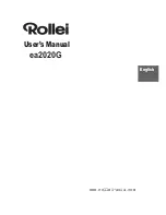
NW-WM1A/WM1Z

DIGITAL MUSIC PLAYER

9-896-325-01

2016J33-1

© 

2016.10

US Model

Canadian Model

NW-WM1Z

AEP Model

UK Model

E Model

Australian Model

Chinese Model

Tourist Model

NW-WM1A/WM1Z

Ver. 1.0  2016.10

SPECIFICATIONS

Note:

Be sure to keep your PC used 
for service and checking of this 
unit always updated with the 
latest version of your anti-virus 
software.
In case a virus affected unit was 
found during service, contact 
your Service Headquarters. 

CAUTION

Danger of explosion if battery is incorrectly replaced.
Replace only with the same or equivalent type.

•  Headphones and microSD card are not supplied with this unit.

Display

Interface

Bluetooth

Bluetooth Specifications

Size/resolution 4.0-inch (10.2 cm) / FWVGA (854 × 480 Pixels)

Panel type

TFT color display with white LED-backlight

Capacitive touch screen

USB

Hi-Speed USB (USB 2.0 compliant)

Headphone

Stereo mini-jack, Balanced standard-jack

WM-PORT

WM-PORT (multiple connecting terminal): 22 pins

External memory

microSD

microSDHC

microSDXC

Communication system

Bluetooth Specification Version 4.2

Frequency band

2.4 GHz band (2.4000 GHz - 2.4835 GHz)

Modulation method

FHSS

Compatible Bluetooth profiles (*1) A2DP (Advanced Audio Distribution Profile)

AVRCP (Audio Video Remote Control Profile)

Supported Codec (*2)

SBC (*3), LDAC

Bluetooth profiles are standardized according to the purpose of the Bluetooth device.

*1

Codec indicates the audio signal compression and conversion format.

*2

SBC stands for Subband Codec.

*3

Output (headphones)

General

Frequency

Frequency response

20 Hz to 40,000 Hz

(when playing data file, single signal measurement)

Power Source

Built-in Rechargeable lithium-ion Battery

USB power (from a computer via a USB connector of the player)

Charging Time

USB-based charging

Approx. 7 hours

Operating temperature

5°C to 35°C (41 ºF to 95 ºF)

Dimensions (Walkman)

w/h/d, projecting parts not included

Approx. 65.3 mm × 123.4 mm × 19.9 mm

(2.58 inches × 4.86 inches × 0.79 inches)

w/h/d

Approx. 72.9 mm × 124.2 mm × 19.9 mm

(2.87 inches × 4.89 inches × 0.79 inches)

Mass (Walkman)

NW-WM1Z

Approx. 455 g (16.1 oz)

NW-WM1A

Approx. 267 g (9.5 oz)

Dimensions (Leather case)

(NW-WM1Z only)

w/h/d, projecting parts not included

Approx. 81 mm × 132 mm × 29 mm

(31.9 inches × 52.0 inches × 11.5 inches)

Capacity

Actual available memory for other contents (*1)

NW-WM1Z 256 GB

NW-WM1A 128 GB

NW-WM1Z Approx. 230.60 GB = 247,612,538,880 byte

NW-WM1A Approx. 114.15 GB = 122,573,127,680 byte

Available capacity may vary. A portion of the memory is used for data management functions.

*1

Photo: NW-WM1A

Photo: NW-WM1Z

Summary of Contents for WALKMAN NW-WM1A

Page 1: ...tible Bluetooth profiles 1 A2DP Advanced Audio Distribution Profile AVRCP Audio Video Remote Control Profile Supported Codec 2 SBC 3 LDAC Bluetooth profiles are standardized according to the purpose of the Bluetooth device 1 Codec indicates the audio signal compression and conversion format 2 SBC stands for Subband Codec 3 Output headphones General Frequency Frequency response 20 Hz to 40 000 Hz w...

Page 2: ...it Sampling frequency 2 8224 5 6448 11 2896 MHz Note Files that are 4 GB or larger cannot be played back This product recognizes audio sources exceeding CD quality 44 1 kHz 16 bit quantization and DAT quality 48 kHz 16 bit quantization as High Resolution Audio The HR symbol is displayed for High Resolution Audio sources Sampling frequency may not correspond to all encoders 1 Copyright protected fi...

Page 3: ...k Hook B Balanced Standard Side 23 2 13 MAIN Board Block 1 24 2 14 MAIN Board Block 2 25 2 15 HP SE Assy Block Stereo Mini Side MAIN Board 26 2 16 HP SE Assy HPJ1 Stereo Mini Side 27 2 17 HP BTL Assy Block Balanced Standard Side 27 2 18 HP BTL Assy HPJ2 Balanced Standard Side 28 2 19 HOLD NFC FPC Assy FPC1 29 2 20 PWB Chassis 30 2 21 Strap Holder Assy Card Lid Assy 31 2 22 Hinge Stopper Escutcheon...

Page 4: ... JE Tourist model The SERVICING NOTES contains important information for servicing Be sure to read this section before repairing the unit METHOD OF DISTINGUISHING THE WALKMAN MAIN UNIT When distinguish the destination of the WALKMAN main unit check by following method Method of using the tool Note 1 Check before you replace the MAIN board of the repairing unit to perform this method If the WALKMAN...

Page 5: ... non consistent ver sion transfer tool an error occurs in the middle of the transfer Tool name in the above table does not described the version rep resent as Vx xx xx Please check the firmware version of the WALKMAN main unit beforehand Note 4 Each tools using by OS of Windows 7 or later Note 5 If you want to run the each tools please close the SonicStage x Application Media Go etc applications P...

Page 6: ...pdate tool has booted The firmware of drive f will be updated After the new firmware is copied to drive f the new firmware will be loaded and the unit will reboot Close SonicStage before starting this program Run this program y n Using 2 byte characters it may not be displayed correctly Input 9 The following figure message is displayed and the destination model settings is performed on the WALKMAN...

Page 7: ...etter of checked at step 2 C NWXXXX_Color_Init_Setting_V1 00 BLACK updating bat f WM1A or WM1Z Input 8 Check that the following figure message has been displayed and input y and press the Enter key The firmware update tool has booted The firmware of drive f will be updated After the new firmware is copied to drive f the new firmware will be loaded and the unit will reboot Close SonicStage before s...

Page 8: ...er key get_model_info bat f f is drive letter of checked at step 2 C NWWM1_A30_ModelInfo V1 00 get_model_info bat f Input 8 It will appear the following figure results Displayed characters values in the following figure are ex ample Destination code number Bundled headphone code number NAND capacity code number Body color code number Model ID code number 9 Check the code number of each items Model...

Page 9: ...erate on the PC personal com puter 2 Check how the WALKMAN is recognized by MSC connec tion and the check of the drive letter is necessary at this example it is F 3 Open the folder that the pre installed contents and open the WALKMAN storage 4 Copy the opt3 folder in the pre installed contents folder to the under root directory of the WALKMAN storage In the folder of pre installed contents Copy he...

Page 10: ...ration state t Settings t Device Settings of Basic Settings t Reset Format t Restore to Factory Configuration t Yes t Yes 13 The WALKMAN is rebooting 14 After the WALKMAN is rebooted language date time of ini tial setup wizard to complete and connect the WALKMAN main unit to PC personal computer by the USB cable WM PORT USB cable 15 On PC personal computer open the WALKMAN storage Folders and cont...

Page 11: ...n Note 1 It can not be connected when the WALKMAN screen is off Note 2 Continue to touch until instructed appear on the WALKMAN screen 2 If the NFC connection is normal the pop up menu shown in the figure below is displayed on the WALKMAN screen Note 3 If there is a problem with the connection you are not presented with the pop up menu Note 4 If there is a problem with the connection not display t...

Page 12: ... connection checking is complete Yes Replace a new HOLD NFC FPC board NFC connection checking is complete Yes Replace the MAIN board as a result of perform the NFC connection check pop up menu is displayed NFC connection checking is completion Yes No State that does not removed the HOLD NFC FPC board from the main unit releases the connection between the NFC antenna Then a new HOLD NFC FPC board c...

Page 13: ...performance if you reformat the memory of the WALKMAN using a computer Rebuild Database This operation rebuilds the database on the WALKMAN You can rebuild the database manually If you rebuild the database the following informa tion will be erased Elapsed time of the selected track Playback order Restore to Factory Configura tion This operation initializes both the settings and internal memory You...

Page 14: ... Page 24 2 14 MAIN BOARD BLOCK 2 Page 25 2 15 HP SE ASSY BLOCK STEREO MINI SIDE MAIN BOARD Page 26 2 16 HP SE ASSY HPJ1 STEREO MINI SIDE Page 27 2 8 ANTENNA WIFI BT ANT1 Page 19 2 9 CABLE HOLDER Page 20 2 17 HP BTL ASSY BLOCK BALANCED STANDARD SIDE Page 27 2 19 HOLD NFC FPC ASSY FPC1 Page 29 2 20 PWB CHASSIS Page 30 2 11 JACK RING S JACK HOOK S STEREO MINI SIDE Page 22 2 12 JACK RING B JACK HOOK B...

Page 15: ...and attach in the order below front side top side bottom side 2 rear cover assy 1 Lift the rear cover assy while slowly peeling off the adhesive sheet rear from the corner of the bottom side hole rib 2 screw NDS EL M1 4 u 3 1 two screws NDS EL M1 4 u 4 2 two screws NDS EL M1 4 u 3 4 two claws 2 screw NDS EL M1 4 u 3 5 rear support assy upper top side front side bottom side 3 rear support lower Not...

Page 16: ...p side 1 sheet NFC FPC 2 Unlock the connector CN7052 3 Draw the antenna NFC out of the connector 3DVWLQJ SRVLWLRQ RI WKH VKHHW 1 3 guide line sheet NFC FPC top side 6 Peel the HOLD NFC FPC off of the battery case assy HOLD NFC FPC 3DVWLQJ SRVLWLRQ RI WKH 2 1 3 guide line top side 5 adhesive sheet FPC side Note Adhesive sheet FPC side cannot be reused Be sure to replace them with new parts Also com...

Page 17: ...ire black as shown in the figure below bottom side guide line sheet battery solder sheet battery solder 3DVWLQJ SRVLWLRQ RI WKH VKHHW EDWWHU VROGHU 8 battery assy block 2 sheet battery solder 1 Lift up the battery assy block in the direction of the arrow 3 Remove the solder black Note 2 Perform insulation such as taping the battery wire ends 5 Remove the solder black Note 2 Perform insulation such...

Page 18: ...y from the adhesive sheet BATT the lithium ion storage battery cannot be reused Be sure to replace them with new parts 3 Peel the lithium ion storage battery off of the adhesive sheet BATT Note When removing the lithium ion storage battery from the adhesive sheet BATT the lithium ion storage battery cannot be reused Be sure to replace them with new parts 5 battery case assy NFC1 adhesive sheet BAT...

Page 19: ...onnector connector Insert vertically coaxial cable coaxial cable coaxial cable antenna WIFI BT FPC Connector is peeled off from the FPC FPC is peeled off from the holder antenna WIFI BT holder FPC RZ WR LQVWDOO WKH FRD LDO FDEOH FRQQHFWRU When installing the coaxial cable connector insert vertically and push it from the top coaxial cable bottom side bottom side 1 coaxial cable connector RZ WR LQVW...

Page 20: ...e detector top side sheet wire detector 3DVWLQJ SRVLWLRQ RI WKH VKHHW ZLUH GHWHFWRU 2 stereo mini jack cable connector CN7022 1 sheet wire detector top side front side bottom side 4 screw NDS EL M1 4 u 4 5 cushion CONN support 6 cable holder Note When installing the cable holder check that the cable etc is not pinched before installation 5 cushion CONN support 3 Peel off the KEY LED FPC 3DVWLQJ SR...

Page 21: ...and insert the connector 7 screw NDS EL M1 4 u 5 qa battery spacer Note When installing the battery spacer check that the FPC etc is not pinched before installation 1 battery spacer sheet 9 Remove the battery spacer block in the direction of the arrow 3DVWLQJ SRVLWLRQ RI WKH EDWWHU VSDFHU VKHHW Align the hole top side front side bottom side guide line RZ WR LQVWDOO WKH 2 1 3 2 Align and affix the ...

Page 22: ...otruding jack ring S block hole clip etc top side top side Top view tweezers etc ow Wo iQVWDOO WKe MDFN KooN 6 jack hook S 3 Lock the claw 3 Lock the two claws 4 Rotate the jack hook S counter clockwise to remove the lock 2 Rotate the jack hook S clockwise 1 Align the jack hook S with the hole shape of the cabinet and install front side top side bottom side 5 jack hook S 3 jack ring S 2 adhesive s...

Page 23: ...ant OK NG Raised 4 Rotate the jack hook B counter clockwise to remove the lock RZ WR LQVWDOO WKH MDFN KRRN 1 Align the jack hook B with the hole shape of the cabinet and install 3 Lock the two claws 3 Lock the claw 7RS YLHZ 2 Rotate the jack hook B clockwise top side tweezers etc jack hook B 5 jack hook B 3 jack ring B 2 adhesive sheet ring cabinet hole jack ring B block hole clip etc clip etc Gap...

Page 24: ...hite 5 Remove the solder WM1A white WM1Z natural 1 long wire white L 3 short wire white R 2 long wire natural L 4 short wire natural R top side 2 escutcheon stopper 1 screw NDS EL M1 4 u 5 Solder the wires of the HP BTL assy block in order from 1 to 4 top side MAIN board MAIN board MAIN board short wire of the HP BTL assy block long wire of the HP BTL assy block NW WM1Z NW WM1A RZ WR LQVWDOO WKH H...

Page 25: ...WM1Z NW WM1A front side bottom side groove hole rib rib WM PORT portion adhesive sheet holder LG top side top side adhesive sheet holder LG MAIN board AIIL LQJ WKH FRSSHU UHOD VKHHW 7 MAIN board block Note When installing the MAIN board align the hole and groove on the board with the two ribs on the cabinet block 3 two screws NDS EL M1 4 u 4 4 Lift up the cable and three FPCs in the direction of t...

Page 26: ...tural L 3 short wire white RGND 3 wire black yellow tube LGND 2 long wire white LGND 4 short wire natural R top side top side 7 MAIN board NW WM1Z NW WM1A QVWDOOLQJ WKH ZLUHV RQ WKH VWHUHR PLQL VLGH 1 Remove the solder WM1A white WM1Z natural 2 Remove the solder WM1A black WM1Z white 4 Remove the solder WM1A white yellow tube WM1Z natural 3 Remove the solder WM1A black yellow tube WM1Z white 6 adh...

Page 27: ...ion bottom side front side 5 jack holder B 1 sheet wire detector 1 sheet wire detector sheet strap jack holder B 3 Take out the HP BTL assy block from the hole hole hole 6 HP BTL assy block Note Take care not to peel off the sheet strap top side 3DVWLQJ SRVLWLRQ RI WKH VKHHW ZLUH GHWHFWRU QVWDOODWLRQ GLUHFWLRQ IRU WKH MDFN KROGHU sheet wire detector sheet wire detector 2 HP BTL assy block wire con...

Page 28: ...ire no wire sheet strap wire red short wire white short wire natural long wire white no wire no wire sheet strap wire red wire black yellow tube NW WM1Z NW WM1A NW WM1Z 3 HP BTL assy HPJ2 1 sheet strap 1 sheet strap 2 O ring band sheet strap sheet strap 3DVWLQJ SRVLWLRQ RI WKH VKHHW VWUDS ...

Page 29: ...WDOO WKH NQRE DVV HOLD NFC FPC assy slide switch 1 Align the knob assy and slide switch and then attach them 2 Slide the HOLD switch left and right and check that the slide switch is securely attached to the knob assy 3DVWLQJ SRVLWLRQ RI WKH 2 1 3 alignment mark adhesive side top side 2 Peel the HOLD NFC FPC off of the cabinet 1 relay copper sheet 3 screw SG M1 4 4 knob assy 5 HOLD NFC FPC assy FP...

Page 30: ...nt side top side bottom side bottom side protection sheet PWB 3DVWLQJ SRVLWLRQ RI WKH SURWHFWLRQ VKHHW 3 bottom side guide line PWB chassis 3DVWLQJ SRVLWLRQ RI WKH SURWHFWLRQ VKHHW 3 Chassis block front view RF cushion 3DVWLQJ SRVLWLRQ RI WKH 5 FXVKLRQ adhesive sheet holder LG RF cushion PWB chassis 1 Peel the light guide card block off of the light guide holder 3 Peel the light guide holder block...

Page 31: ...card lid 5 Remove the card lid assy block 6 Draw the card lid assy shaft out of the hole 7 escutcheon card 8 card lid assy 1 screw NDS EL M1 4 u 3 QVWDOODWLRQ GLUHFWLRQ IRU WKH VWUDS KROGHU DVV DQG FDUG OLG DVV EORFN 4 three screws SG M1 4 5 KEY LED FPC assy FPC2 hole 3 escutcheon multi Note When installing the escutcheon multi align the rib and hole front side top side bottom side 1 screw SG M1 4...

Page 32: ...ssy 8 light guide CHG 7 adhesive sheet LG CHG 9 serial number panel 0 jack cushion 3DVWLQJ SRVLWLRQ RI WKH OLJKW JXLGH slit LCD FPC LCD assy LCD1 2 Push out the LCD assy block from the slit in the direction of the arrow using a flat tipped tool etc flat tipped tool etc light guide CHG adhesive sheet LG CHG top side bottom side top side NW WM1Z 3 Draw the LCD FPC out of the hole LCD sheet cabinet U...

Page 33: ...the folder and put a cursor to blank space in the folder Folder window of tool for the test mode blank space cursor 7 The right click while pressing the Shift key in the state of step 6 8 Select the Open command window here from the displayed menu and launch the command prompt application software 9 Input the following command and press the Enter key updating bat f f is drive letter of checked at ...

Page 34: ...E u key Major item Major item switching keys HOLD switch on Minor item Finish or Result Start Automatic u key or key key or HOLD switch on Minor item switching keys 5 OPERATION OF THE TEST MODE 5 1 Power Power Diagnosis APP ver X XX XX Screen display Power Voltage check Current check DeepSleep check Charge check Battery voltage Battery status Thermistor check 5 1 1 Power supply voltage check Volta...

Page 35: ... the u or key to enter the minor item 3 Press the keys to select the DeepSleep check 4 Press the u key enter the state of the deep sleep Screen display is turned off 5 In step 4 state check the measuring the consumption current in standby 6 Sleep is released by pressing any key button of WALKMAN main unit Power DeepSleep POW DSVC command idle state Screen display 7 Slide the HOLD switch in the dir...

Page 36: ...mis tor voltage value is updated 6 Slide the HOLD switch in the direction of on to return to minor item selection screen 5 2 Audio Audio Diagnosis APP ver X XX XX Screen display Audio Output sound check S N check Frequency check1 Frequency check2 Separation L check Separation R check Max output check Normalizer Sound pressure Play user file 1 Play user file 2 Play user file 3 Play user select Outp...

Page 37: ...the HOLD switch in the direction of on to return to minor item selection screen 5 2 4 Frequency response check 2 Frequency check2 It can be output the Sampling rate 44 1 kHz Frequency 20 kHz L R ch Bit rate 16 bit audio signal for the frequency response check Procedure 1 Enter the test mode Refer to 2 SETTING THE TEST MODE on page 33 2 Press the keys to select the Audio and press the u or key to e...

Page 38: ... not change the volume It has been fixed at the maximum value 120 6 Slide the HOLD switch in the direction of on to return to minor item selection screen 5 2 8 Normalizer check Normalizer It can be output the Sampling rate 44 1 kHz Frequency 1 kHz L R ch Bit rate 16 bit audio signal for the normalizer check Procedure 1 Enter the test mode Refer to 2 SETTING THE TEST MODE on page 33 2 Press the key...

Page 39: ...o return to minor item selection screen 5 3 Video Video Diagnosis APP ver X XX XX Screen display Video LCD panel check 5 3 1 LCD panel check LCD panel check It can be check the LCD screen display Procedure 1 Enter the test mode Refer to 2 SETTING THE TEST MODE on page 33 2 Press the keys to select the Video and press the u or key to enter the minor item 3 Press the keys to select the LCD panel che...

Page 40: ...alues in the following figure are ex ample NFC test tools NFC RTAG command oooooooooo oooooooooo oooooooooo oooooooooo oooooooooo oooooooxxx xxxxxxxxxx xxxxxxxxxx xxxxxxxooo oooooooooo Detect tag test 70 100 Screen display 5 Detection is performed every 100 milliseconds If detect the NFC tag to be displayed O If not detect the NFC tag to be displayed X Note Detection history will be displayed up t...

Page 41: ...Touch locus pink Coordinate values Pressure values Status released or pressed 6 Press the key and erase the touch locus 7 Slide the HOLD switch in the direction of on to return to minor item selection screen 5 10 2 Cross check Cross check It can be displayed the black line of touch locus of touch panel and change the line dot Note It can not operate in a state in which the WALKMAN main unit was MS...

Page 42: ...played Displayed value in the following figure is example fw version TCH VERS command vender product version driver 0 0 0 10001 Screen display Note If the information is not set or if an invalid value set is dis played 5 Slide the HOLD switch in the direction of on to return to minor item selection screen 5 11 Key Key Diagnosis APP ver X XX XX Screen display Key Press check Press count check Conne...

Page 43: ... screen is changed into OK Displayed characters values in the following figure are ex ample RTC check OTR RTCC command Clock information Fri Sep 02 2016 13 28 07 641628 testing Screen display date time testing r OK 6 Slide the HOLD switch in the direction of on to return to minor item selection screen 5 15 2 Destination setting Set destination Note Not used for the servicing 5 15 3 Sound pressure ...

Page 44: ...nd Bundle HP NOHP Screen display NOHP Not bundled headphone 5 Slide the HOLD switch in the direction of on to return to minor item selection screen 5 15 8 Color variation check Color variation It can be check the information of the WALKMAN main unit body color Procedure 1 Enter the test mode Refer to 2 SETTING THE TEST MODE on page 33 2 Press the keys to select the Others and press the u or key to...

Page 45: ...G THE TEST MODE on page 33 2 Press the keys to select the Others and press the u or key to enter the minor item 3 Press the keys to select the MSC control 4 Press the u key the control screen is displayed MSC control OTR MASS command MSC control disconnect set Screen display disconnect or connect 5 In this state each time the keys are pressed MSC connection disconnection is select connect disconne...

Page 46: ... test mode status Procedure 1 Enter the test mode Refer to 2 SETTING THE TEST MODE on page 33 2 Press the keys to select the Shutdown and press the u or key to enter the minor item 3 Press the keys to select the PowerOFF normal 4 Press the u key the execution screen is displayed Shutdown SHT EXIT command ShutDown exit diag push PLAY key Screen display 5 Press the u key then shutdown When after the...

Page 47: ...sis APP ver X XX XX Screen display Log Initialize log Add log Show log Copy log 5 17 1 Initialize log data Initialize log It can be initialized log data recorded to NVP Procedure 1 Enter the test mode Refer to 2 SETTING THE TEST MODE on page 33 2 Press the keys to select the Log and press the u or key to enter the minor item 3 Press the keys to select the Initialize log 4 Press the u key the execu...

Page 48: ...screen is displayed Log file copy LOG COPY command copy OK Screen display 5 Press the u key copy is performed and create the log txt to the under root directory of the WALKMAN main unit storage 6 Slide the HOLD switch in the direction of on to return to minor item selection screen 7 Refer to 5 16 4 Reboot test mode release and releasing the test mode status 8 Connect the WALKMAN main unit to PC pe...

Page 49: ...inet s Color 4 1 REAR COVER SECTION battery section 1 1 3 2 4 5 6 5 6 5 5 8 7 1 4 590 471 01 SHEET RING ADHESIVE 2 4 590 446 01 RING B JACK for Balanced Standard side 3 4 590 445 01 RING S JACK for Stereo Mini side 4 X 2594 175 1 SVX SUPPORT UPPER REAR ASSY Including Cushion 5 4 573 907 11 SCREW NDS EL M1 4 L 3 mm 6 4 573 907 21 SCREW NDS EL M1 4 L 4 mm 7 X 2594 169 1 SVX COVER REAR ASSY Including...

Page 50: ...circuited of the battery wire part of the battery assy Ref No BAT1 51 4 545 100 01 SHEET NFC FPC 52 4 590 479 01 SHEET PWB COVER 53 4 573 907 21 SCREW NDS EL M1 4 L 4 mm 54 4 590 480 01 HOLDER CABLE 55 4 566 912 01 CUSHION CONN SUPPORT 56 4 593 949 01 SHEET WIRE DETECTOR 57 4 591 297 01 SHEET BATTERY SOLDER 58 4 599 959 01 CUSHION PWB 59 4 684 878 01 CUSHION MULTI 60 4 569 120 01 SHEET FPC SIDE AD...

Page 51: ...OMPLETE SV Including Electric double layers cap Coaxial cable Wire Adhesive sheet Sheet Cushion WM1A See Note 107 9 885 214 07 MAIN BOARD COMPLETE SV Including Electric double layers cap Coaxial cable Wire Adhesive sheet Sheet Cushion WM1Z See Note 108 4 687 782 01 CUSHION RELAY 109 4 593 943 01 SHEET HOLDER LG ADHESIVE 110 4 593 940 01 CUSHION FPC BUTTON 111 3 234 449 37 SCREW M1 4 L 4 mm 112 4 5...

Page 52: ...PPER HINGE 164 4 590 478 01 CUSHION JACK 165 4 593 949 01 SHEET WIRE DETECTOR 166 4 590 448 01 HOLDER B JACK for Balanced Standard side 167 4 590 456 01 ESCUTCHEON CARD WM1A 167 4 590 456 11 ESCUTCHEON CARD WM1Z 168 4 573 907 11 SCREW NDS EL M1 4 L 3 mm 169 X 2594 179 1 SVX LID CARD ASSY Including O ring WM1A 169 X 2594 180 1 SVX LID CARD ASSY H Including O ring WM1Z 170 X 2594 181 1 SVX HOLDER ST...

Page 53: ...sheet Sheet WM1A E AUS JE 205 X 2594 202 1 SVX CABINET ASSY H Including LCD support top Button Dot pin Button hinge Adhesive sheet Sheet WM1Z US CND 205 X 2594 203 1 SVX CABINET ASSY H Including LCD support top Button Dot pin Button hinge Adhesive sheet Sheet WM1Z AEP UK 205 X 2594 204 1 SVX CABINET ASSY H Including LCD support top Button Dot pin Button hinge Adhesive sheet Sheet WM1Z EE 205 X 259...

Page 54: ...OLISH AEP UK 4 593 854 21 MANUAL INSTRUCTION ENGLISH FRENCH SPANISH US CND 4 593 854 31 MANUAL INSTRUCTION ENGLISH RUSSIAN SIMPLIFIED CHINESE TRADITIONAL CHINESE KOREAN ARABIC E AUS JE EE 4 593 854 41 MANUAL INSTRUCTION ENGLISH SIMPLIFIED CHINESE CH 501 1 835 940 61 CORD PC CONNECTION USB cable 502 4 594 129 01 STRAP HAND Wrist strap 503 4 594 482 01 LEATHER CASE WM1Z 503 Leather case 1 501 USB ca...

Page 55: ...MEMO NW WM1A WM1Z 55 ...

Page 56: ...NW WM1A WM1Z REVISION HISTORY Ver Date Description of Revision 1 0 2016 10 New ...

Reviews: