Sony VPL-VW200 - SXRD Projector - HD 1080p, Operating Instructions Manual
The Sony VPL-VW200 is a high-quality SXRD projector capable of projecting stunning HD 1080p images. For easy setup and optimal use, be sure to download the free Operating Instructions Manual from manualshive.com, providing detailed guidance and ensuring you get the most out of this exceptional home theater projector.
Share
Download


Reviews:
No comments
Related manuals for VPL-VW200 - SXRD Projector - HD 1080p

1720
Brand: 3M Pages: 9

WT615 Series
Brand: NEC Pages: 159

VT695
Brand: NEC Pages: 2

U300X Series
Brand: NEC Pages: 2

H2
Brand: GEARGO Pages: 60

LC-XlU
Brand: Eiki Pages: 52

Low-Profile Dedicated Projector Mount PDS-020
Brand: Premier Mounts Pages: 2

VideoMate 2250
Brand: Navitar Pages: 24
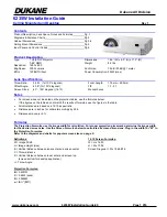
6235W
Brand: Dukane Pages: 6

DATA 8200
Brand: Barco Pages: 52

907 052
Brand: Bodet Pages: 2

PowerLite 460
Brand: Epson Pages: 4

PLC-XT10
Brand: Sanyo Pages: 2

PLC-XP51
Brand: Sanyo Pages: 2

PLC-XP45
Brand: Sanyo Pages: 1

PLC-XT10
Brand: Sanyo Pages: 48

PLC-XP50
Brand: Sanyo Pages: 56

PLC-XR301 - XGA Projector With 3000 Lumens
Brand: Sanyo Pages: 77


