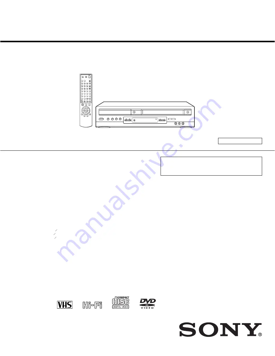
background image

US Model

SERVICE MANUAL

DVD PLAYER/

VIDEO CASSETTE RECORDER

SPECIFICATIONS

SLV-D300P

RMT-V501A

System

Laser

Semiconductor laser

Format

VHS NTSC standard

Video recording system

Rotary head helical scanning FM system

Video heads

Double azimuth four heads

Video signal

NTSC color, EIA standards

Tape speed

SP: 33.35 mm/s (1 


inches/s)

EP: 11.12 mm/s (


inches/s)

LP: 16.67 mm/s (


inches/s),

playback only

Maximum recording/playback time

8 hrs. in EP mode (with T-160 tape)

Rewind time

Approx. 1 min (with T-120 tape)

Tuner section

Channel coverage

VHF 2 to 13
UHF 14 to 69
CATV A-8 to A-1, A to W, W+1 to W+84

Antenna

75-ohm antenna terminal for VHF/UHF

Audio characteristics

Frequency response 

DVD VIDEO (PCM 96 kHz): 2 Hz to 44 kHz (

±

1.0 

dB)/DVD VIDEO (PCM 48 kHz): 2 Hz to 22 kHz 
(

±

0.5 dB)/CD: 2 Hz to 20 kHz (

±

0.5 dB)

Signal-to-noise ratio (S/N ratio)

115 dB (LINE OUT (L/R) AUDIO jacks only)

Harmonic distortion

 0.003 %

Dynamic range

DVD VIDEO: 103 dB/CD: 99 dB

Wow and flutter

Less than detected value (

±

0.001% W PEAK)

The signals from LINE OUT L/R (AUDIO) jacks are 
measured. When you play PCM sound tracks with a 96 
kHz sampling frequency, the output signals from the 
DIGITAL OUT (OPTICAL or COAXIAL) jack are 
converted to 48 kHz sampling frequency.

Inputs and outputs

LINE IN 1 and LINE-2 IN

VIDEO IN, phono jack (1 each)
Input signal: 1 Vp-p, 75 ohms, unbalanced, sync 
negative
AUDIO IN, phono jacks (2 each)

Input level: 327 mVrms
Input impedance: more than 47 kilohms

LINE OUT

VIDEO OUT, phono jack (1)

Output signal: 1 Vp-p, 75 ohms, unbalanced, sync 
negative
AUDIO OUT, phono jacks (2)

Standard output: 327 mVrms
Load impedance: 47 kilohms
Output impedance: less than 10 kilohms

DIGITAL OUT

OPTICAL, Optical output jack

18 dBm (wave length: 660 nm)

COAXIAL, phono jack

Output signal: 0.5 Vp-p, 75 ohms

COMPONENT VIDEO OUT (Y, Pb, Pr)

Phono jack
Y: 1.0 Vp-p/Pb, Pr: 0.7 Vp-p, 75 ohms

S-VIDEO OUT

4-pin, mini-DIN jack

Y: 1.0 Vp-p, unbalanced, sync negative
C: 0.286 Vp-p, load impedance 75 ohms

Timer section

Clock

Quartz locked

Timer indication

12-hour cycle

Timer setting

8 programs (max.)

3

8

7

16

11

16

General

Power requirements

120 V AC, 60 Hz

Power consumption

28 W

Operating temperature

0

°

C to 45

°

C (32

°

F to 113

°

F)

Storage temperature

20

°

C to 60

°

C (

4

°

F to 140

°

F)

Operating humidity

25% to 80%

Dimensions including projecting parts and controls 
(w/h/d)

Approx. 430 

×

 95 

×

 295 mm

(Approx. 17 

×

 3.7 

×

 12 inches) 

Mass

Approx. 4.0 kg (Approx. 8.8 lbs)

Supplied accessories

Remote commander (1)
Size AA (R6) batteries (2)

75-ohm coaxial cable with F-type connectors (1)
Audio/video cord (pinplug 

×

 3 

y

 pinplug 

×

 3) (1)

Design and specifications are subject to change without
notice.


Refer to the SERVICE MANUAL of VHS MECHANI-

CAL ADJUSTMENT MANUAL VII for MECHANICAL

ADJUSTMENTS. (9-921-790-11)

TS-10 MECHANISM

Summary of Contents for SLV-D300P Operating Instructions (SLVD300P)

Page 1: ...2 IN VIDEO IN phono jack 1 each Input signal 1 Vp p 75 ohms unbalanced sync negative AUDIO IN phono jacks 2 each Input level 327 mVrms Input impedance more than 47 kilohms LINE OUT VIDEO OUT phono jack 1 Output signal 1 Vp p 75 ohms unbalanced sync negative AUDIO OUT phono jacks 2 Standard output 327 mVrms Load impedance 47 kilohms Output impedance less than 10 kilohms DIGITAL OUT OPTICAL Optical ...

Page 2: ...instruments 2 A battery operated AC milliammeter The Data Precision 245 digital multimeter is suitable for this job 3 Measuring the voltage drop across a resistor by means of aVOM or battery operated AC voltmeter The limit indication is 0 75V so analog meters must have an accurate low voltage scale The Simpson 250 and Sanwa SH 63Trd are examples of a passiveVOM that is suitable Nearly all battery ...

Page 3: ...or Removal 2 15 2 4 19 Lever Unit Pinch Ass y Plate Joint Spring Pinch Drive Removal 2 16 2 4 20 Lever 9 Guide Ass y Removal 2 16 2 4 21 FE Head Removal 2 17 2 4 22 ACE Head Removal 2 17 2 4 23 Slider S T Ass y Removal 2 18 2 4 24 Plate Ground Deck Cylinder Ass y Removal 2 18 2 4 25 Belt Pulley Removal 2 19 2 4 26 Motor Capstan Ass y Removal 2 19 2 4 27 Post 8 Guide Ass y Removal 2 20 2 4 28 Level...

Page 4: ...customer 4 Insulation Resistance Test Cold Check 1 Unplug the power supply cord and connect a jumper wire between the two prongs of the plug 2 Turn on the power switch of the instrument 3 Measure the resistance with an ohmmeter between the jumpered AC plug and all exposed metallic cabinet parts on the instrument such as screwheads antenna control shafts handle brackets etc When an exposed metallic...

Page 5: ... them with components rated for higher voltage wattage etc Parts that have special safety characteristics are identified by shading an or a on schematics and parts lists Use of a substitute replacement that does not have the same safety characteristics as the recommended replacement part might create shock fire and or other hazards Product safety is under review continuously and new instructions a...

Page 6: ... service precautions are indicated or printed on the cabinet chassis or components When servicing follow the printed or indicated service precautions and service materials 3 The components used in the unit have a specified flame resistance and dielectric strength When replacing components use components which have the same ratings Components identified by shading by or by in the circuit diagram ar...

Page 7: ...sembly 3 Use only a grounded tip soldering iron to solder or unsolder ESD devices 4 Use only an anti static solder removal devices Some solder removal devices not classified as anti static can generate electrical charges sufficient to damage ESD devices 5 Do not use freon propelled chemicals These can generate electrical charges sufficient to damage ESD devices 6 Do not remove a replacement ESD de...

Page 8: ...s them the same ground as the sheet 4 Remove the optical pick up block 5 Perform work on top of the conductive sheet Be careful not to let your clothes or any other static sources to touch the unit Be sure to put on a wrist strap grounded to the sheet Be sure to lay a conductive sheet made of copper etc Which is grounded to the table Fig 3 6 Short the short terminal on the PCB which is inside the ...

Page 9: ...der land 2 points short on Pick up See Fig 4 4 Disassembly the Pick up 5 2 Assembly 1 Replace the Pick up 2 Remove the soldering 2 points on Pick up 3 Reassemble the Deck Assy Note If the assembly and disassembly are not done in correct sequence the Pick up may be damaged PICK UP ASS Y SOLDER LAND 2 POINTS SHORT Fig 4 ...

Page 10: ... 10 MEMO ...

Page 11: ...at your TV TV DVD VIDEO Remote sensor continued SELECT VIDEO SELECT DVD 10 Setting up the remote commander Controlling other TVs with the remote commander The remote commander is preprogramed to control non Sony TVs If your TV is listed in the following table set the appropriate manufacturer s code number Now you can use the 1 VOL CH MUTING TV VIDEO and ENTER buttons to control your TV You can als...

Page 12: ...your DVD VCR to record programs you only need to make the connections shown on this page If you want to record regular or cable TV programs complete these connections first and then go to the following pages for antenna or cable hookups A Use this hookup if your TV has stereo jacks B Use this hookup if your TV does not have stereo jacks Notes To play a tape disc in stereo you must use the A V conn...

Page 13: ... Step 4 Selecting a language on page 19 The clock is set using a time signal provided by some TV channels If the clock is incorrect or appears in the display window see Using Manual Clock Set on page 22 To add or disable channels manually see Presetting disabling channels manually on page 26 AC power cord to AC outlet continued 18 Basic hookups Hookup 3 Connecting a cable box with many scrambled c...

Page 14: ...or Daylight saving Select Yes or No standard time or Auto to have the DVD VCR automatically set the daylight saving time 5 Press O RETURN repeatedly to exit the menu 6 To activate the Auto Clock Set function turn off the DVD VCR continued 22 Setting the clock Notes The clock cannot be set automatically if you do not receive a channel that carries a time signal in your area If so set the clock manu...

Page 15: ... cable TV channels Press B b to select Cable TV To preset VHF and UHF channels Press B b to select Antenna 5 Press V v to select Auto channel memory then press ENTER All receivable channels are preset in numerical sequence When no more receivable channels can be found presetting stops and the picture from the lowest numbered channel is displayed on the TV screen continued 26 Presetting channels Pr...

Page 16: ...everse and slow motion play cannot be paused When playing a chapter with multi angles on a DVD in slow motion you cannot change the slow motion playback speed 1 2 only During CD fast forward reverse play no sound is output The PROGRESSIVE button is not available when the DVD player is in play mode Use the PROGRESSIVE button in stop mode Notes on playing DTS sound tracks on a CD When playing DTS en...

Page 17: ...eration View the picture during fast forward or rewind During fast forward hold down M During rewind hold down m Play at high speed During playback briefly press M or m The tape continues to play at 5 times normal speed During playback hold down M or m The tape continues to play at 5 times normal speed When you release the button normal playback resumes Hour Minute Second 35 Playing a tape Basic O...

Page 18: ...l number then press ENTER You can select a video source from the LINE IN 1 or LINE 2 IN jacks using the INPUT SELECT button The display appears on the TV screen indicating information about the tape but the information will not be recorded on the tape If you do not want to watch TV while recording you can turn off the TV When using a cable box make sure to leave it on Notes The remaining tape leng...

Page 19: ...tch another TV program after setting the timer To watch a DVD after setting the timer Tips To set the channel you can also use V v If the indicator appears the timer settings overlap To check change or cancel the program setting repeat the steps of Recording TV programs using the timer on page 39 If the indicator appears this means that the VCR is currently recording this program You can also do t...

Page 20: ...not supplied Remove jack cap before connecting 46 S Video Component Video hookup S Video Component Video hookup Make audio connections using the LINE OUT AUDIO L R jacks or DIGITAL AUDIO OUT OPTICAL or COAXIAL jacks on the right side of the DVD VCR when you use S VIDEO Component Video hookup A Use this hookup if your TV has an S VIDEO input jack Connect an S VIDEO cord not supplied You will enjoy ...

Page 21: ...ress O RETURN repeatedly to exit the menu D PCM Select this when the player is connected to an audio component lacking a built in Dolby Digital decoder Dolby Digital Select this when the player is connected to an audio component with a built in Dolby Digital decoder Off Select this when the player is connected to an audio component lacking a built in DTS decoder On Select this when the player is c...

Page 22: ...If you select progressive signal when you connect the DVD player to a TV that cannot accept the signal in progressive format the image quality will deteriorate In this case press the PROGRESSIVE button to turn off the PROGRESSIVE indicator You can output progressive signal only from COMPONENT VIDEO OUT jacks If you turn on the PROGRESSIVE indicator when you set Video Out to S video COMPONENT VIDEO...

Page 23: ...4 digit password using the number buttons The player starts playback 1 Remove the disc and turn off the DVD VCR 2 Turn on the DVD VCR again with no disc in the unit 3 Hold down m and M on the front panel simultaneously for 5 seconds reset ok appears on the screen 4 Turn off the DVD VCR The password is cleared 5 To create a new password follow step 4 on page 57 59 Using the DVD s menu DVD Additiona...

Page 24: ...selected angle ANGLE B b 62 Displaying the subtitle Displaying the subtitle To turn off the subtitles Select Off in step 3 Note Depending on the DVD you may not be able to change the subtitles even if multilingual subtitles are recorded on it You also may not be able to turn them off If subtitles are recorded on the disc you can change the subtitles or turn them on and off whenever you want while ...

Page 25: ... b repeatedly to select the item to be repeated When playing a DVD Chapter repeats the current chapter Title repeats the current title on a disc When playing a VIDEO CD or CD Track repeats the current track Disc repeats all of the tracks When playing a DATA CD MP3 audio Track repeats the current track REPEAT CLEAR B b 67 Using bookmarks DVD Additional Operations Using bookmarks You can store scene...

Page 26: ... The default setting is indicated in bold print AUDIO B b STEREO The standard stereo sound Left The sound of the left channel monaural Right The sound of the right channel monaural 70 Virtual surround setting Virtual surround setting To cancel the setting Select Off in step 2 When you connect a stereo TV or 2 front speakers SURROUND lets you enjoy surround sound effects by using sound imaging to c...

Page 27: ...5 Playing an MP3 audio track DVD Additional Operations When you insert a DATA CD and press H PLAY the numbered tracks are played sequentially from 1 through 7 Any sub albums tracks contained within a currently selected album take priority over the next album in the same tree Example C contains D so 4 is played before 5 When you press O RETURN and the list of MP3 albums appears page 73 the albums a...

Page 28: ...repeatedly to return to the first ALBUM page To return to the Select a Media Type menu Press x STOP twice then press TOP MENU Notes Slide show can play in only one direction You cannot rotate or zoom in the image during Slide show If you select ALBUM in the rotated image display the images in the ALBUM display will also be rotated Correct the rotation in the ROTATE menu About JPEG image files You ...

Page 29: ...to On screen display Display window Stereo Hi Fi STEREO indicator Left channel Left STEREO indicator Right channel Right STEREO indicator Monaural sound on the normal audio track Mono No indicator Normal audio track Hi fi audio track main track Monaural sound Stereo sound left right channels 83 Searching using various functions VCR Additional Operations Searching using various functions To search ...

Page 30: ...ss SET UP when the DVD player is in stop mode 2 Press V v B b to select Video Function Setup then press ENTER The VIDEO FUNCTION SETUP menu appears 3 Press V v to select the option to change 4 Press B b to change the setting 5 Press O RETURN repeatedly to exit the menu Menu option Set this option to Tape Length T 120 when using a T 120 or shorter length tape T 160 when using a T 160 length tape T ...

Page 31: ...never you use the DVD VCR set the TV to the channel selected in step 1 TV CHANNEL 1 TV VIDEO CH 1 91 General setup information Additional Information Attaching the external antenna connector Attaching a UHF VHF band mixer When using a 300 ohm twin lead cable for a VHF UHF antenna use an antenna connector not supplied to connect the antenna to the DVD VCR 1 Loosen the screws on the antenna connecto...

Page 32: ...e player Moisture has condensed inside the player page 3 The player cannot play CD Rs CD RWs or DVD Rs that are not finalized page 7 Make sure the TV DVD VIDEO switch is set correctly Select correctly VIDEO or DVD with SELECT DVD VIDEO button The MP3 audio track cannot be played page 72 The DATA CD is not recorded in the MP3 format that conforms to ISO9660 Level 1 Level 2 or Joliet The MP3 audio t...

Page 33: ...4 N X pause button 29 34 O H play button 29 34 P PROGRESSIVE button indicator 47 53 continued 97 Glossary Additional Information Glossary Chapter page 31 Sections of a picture or a music feature that are smaller than titles A title is composed of several chapters Depending on the disc no chapters may be recorded Dolby Digital page 44 and 49 Digital audio compression technology developed by Dolby L...

Page 34: ...82 J BOOKMARK SEARCH MENU button 67 83 for DVD BOOKMARK button for VIDEO SEARCH MENU button K REPEAT REPLAY button 34 64 for DVD REPEAT button for VIDEO REPLAY button L C SKIP button 29 35 M z REC record button 37 N H PLAY button 29 34 O V v B b button 19 P DISPLAY button 31 37 Q TOP MENU button 59 Number 5 AUDIO and H PLAY buttons have a tactile dot Use the tactile dot as a reference when operati...

Page 35: ...Disabling channels 26 DOLBY DIGITAL 44 69 DTS 45 69 Dubbing see Editing DVD 6 E Editing 87 EP mode 37 H Handling discs 7 Hi fi audio track 82 J JPEG 6 76 L Language selecting 19 LP mode 38 M Monaural 82 Monitoring audio during playback 82 MP3 6 72 N Normal audio track 82 P Palyback MP3 audio track 72 Parental Control 56 PBC Playback control 79 Picture adjustment 85 Playback 28 at various speeds 29...

Page 36: ...1 26E MEMO ...

Page 37: ...abinet Top Removal 2 1 2 Bottom Cover Removal 2 1 3 Ass y Front Panel Removal Fig 2 3 Ass y Front Panel Removal 2 1 4 Function PCB Removal Fig 2 4 Function PCB Removal 2 Lift up the Cabinet Top in the direction of arrow 1 REMOVE 3 SCREWS 1 RELEASE 2 HOOKS 1 RELEASE 4 HOOKS 2 RELEASE 3 HOOKS Top View Bottom View 1 RELEASE 1 HOOK ...

Page 38: ... PCB Removal 1 REMOVE 2 SCREWS 2 REMOVE 4 SCREWS VCR MAIN PCB DVD MAIN PCB VCR DECK 3 REMOVE 3 SCREWS 5 REMOVE 2 SCREWS 4 REMOVE 2 SCREWS DVD DECK 1 REMOVE 3 SCREWS MODE SWITCH When installing the ass y full deck on the Main PCB be sure to align the assembly point of mode switch ASSEMBLY POINT ...

Page 39: ...2 3 Fig 2 7 Circuit Board Locations 2 2 CIRCUIT BOARD LOCATIONS DVD MAIN PCB FUNCTION PCB VCR MAIN PCB ...

Page 40: ... 4 2 3 VCR DECK PARTS LOCATIONS 2 3 1 Top View 1 2 3 4 5 6 1 GEAR FL CAM 2 MOTOR LOADING ASS Y 3 LEVER FL ARM ASS Y 4 HOLDER FL CASSETTE ASS Y 5 LEVER FL DOOR 6 SLIDER DRIVE Fig 2 8 Top parts Location 1 ...

Page 41: ...CYLINDER ASS Y 3 ACE HEAD ASS Y 4 LEVER UNIT PINCH ASS Y 5 LEVER 9 GUIDE ASS Y 6 LEVER TENSION ASS Y 7 BAND BRAKE ASS Y 8 DISK S REEL 9 LEVER S BRAKE ASS Y q GEAR IDLE qa LEVER IDLE qs LEVER T BRAKE ASS Y qd DISK T REEL Fig 2 9 Top Parts Location 2 ...

Page 42: ...2 3 4 5 6 7 8 9 q 1 GEAR JOINT 1 2 GEAR JOINT 2 3 BRAKET GEAR 4 MOTOR CAPSTAN ASS Y 5 LEVER T LOAD ASS Y 6 GEAR LOADING DRIVE 7 LEVER S LOAD ASS Y 8 HOLDER CLUTCH ASS Y 9 BELT PULLEY q SLIDER CAM Fig 2 10 Bottom Parts Location ...

Page 43: ...Lift the Holder FL Cassette Ass y 1 in this time you have to grasp the Lever FL Cassette R 2 Continuously until the Holder FL Cassette Ass y 1 is taken out completely Note Be sure to insert Lever FL Cassette R 2 in the direction of A to prevent separation and breakage of the Lever FL Cassette R 2 at disassembling and reassembling Fig 2 11 Holder FL Cassette Ass y Removal 2 4 2 Lever FL Door Remova...

Page 44: ... Groove of Slider Fl drive 1 Assembly Align the Gear FL Cam 1 with the Gear worm wheel Post as shown drawing Refer to Timing point Fig 2 13 Slider FL Drive Removal Fig 2 14 Gear FL Cam Gear Worm 2 4 4 Lever FL Arm Ass y Removal 1 Push the hole A in the direction of arrow B use the pin about Dia 2 5 2 Pull out the Lever FL Arm Ass y 1 from the Boss of Main Base 3 Remove the Lever FLArmAss y 1 in th...

Page 45: ... Wheel Removal 1 Remove the Gear Worm wheel 1 Fig 2 16 Gear Worm Wheel Removal 2 4 6 Cable Flat Removal 1 Remove the Drum connecting part of Cable Flat 1from Connector Waffer 2 2 Remove the Loading Motor connecting part of Cable Flat 1 from Connector Waffer 3 Fig 2 17 Cable Flat Removal ...

Page 46: ...2 18 Motor Loading Ass y Removal 2 4 8 Bracket Gear Gear Joint 2 1 Removal 1 Remove the SCREW 1 2 Remove the Bracket Gear 2 3 Remove the Gear Joint 2 3 4 Remove the Gear Joint 1 4 Assembly 1 Be sure to align dot mark of Gear Joint 1 1 with dot mark of Gear Joint 2 2 as shown Fig 2 20 Refer to Timing point1 2 Confirm the Timing Point 2 of the Gear Joint 2 2 and Slider Cam 3 Fig 2 19 Bracket Gear Ge...

Page 47: ...to align dot of Lever Load T Ass y 1 with dot of Lever Load S Ass y 2 as shown in drawing Refer to Timing Point 1 2 Insert the Pin A B C D into the Slider Cam 3 hole 3 Be sure to align dot of Lever Load T 1 and dot of Gear Loading Drive 4 Refer to Timing Point 2 4 Aline dot of Gear Loading drive 4 with mark of Slider Cam 3 as shown in drawing Refer to Timing Point 3 Fig 2 22 Gear Loading Drive Sli...

Page 48: ...e S Ass y Refer to Fig 2 25 2 Remove the Spring Tension Lever 1 3 Rotate stopper of Main Base in the direction of arrow A 4 Lift the Lever Tension Ass y 2 Band brake Ass y 3 Note 1 When replacing the LeverTensionAss y 2 be sure to apply Grease on the post 2 Take care not to touch stain on the felt side and not to be folder and broken Band brake Ass y 3 After Lever Tension Ass y seated Rotate stopp...

Page 49: ...nd transformed Spring Brake at removing or reinstalling Fig 2 25 Lever Brake S T Ass y Removal 2 4 14 Gear Idle Ass y Removal 1 Push the Lever Idle 1 in the direction of arrow A B 2 Lift the Lever Idle 1 Assembly 1 Apply oil in two Bosses of Lever Idle 1 2 Assemble the Gear Idle 2 with the Lever Idle 1 Note When replacing the Gear Idle 2 be sure to add oil in the boss of Lever Idle 1 Fig 2 26 Gear...

Page 50: ... Check the condition of spring as shown in detail A 2 Don t push Holder Clutch Ass y down with excessive force Just insert Holder Clutch Ass y into post center with dead force and Rotate it smoothly Be sure to confirm that spring is in the slit of Gear CenterAss y as shown in detail B Fig 2 28 Holder Clutch Ass y Removal 1 DISK S REEL 2 DISK T REEL 1 WASHER SLIT 2 HOLDER CLUTCH ASS Y DETAIL A BAD ...

Page 51: ... Down Ass y 1 for locking of the Hook Note 1 Take care not to separate and sentence does not mark sense 2 Be sure to confirm that Ring of the Gear Center Ass y 2 is in the Guide of the Lever Up Down Ass y 1 after finishing assembly of Lever Up Down Ass y 1 and Gear Center Ass y 2 Fig 2 29 Lever Up Down Ass y Removal Fig 2 30 Lever Up Down Ass y Removal 2 4 18 Guide Cassette Door Removal 1 Lift the...

Page 52: ...st pinch roller Fig 2 32 Lever Unit Pinch Ass y Plate Joint Spring Pinch Drive Removal 2 4 20 Lever 9 Guide Ass y Removal 1 Remove the Spring 9 Guide 1 2 Lift the Spring 9 Guide Ass y 2 in the direction of arrow A Note 1 Take extreme care not to get grease on the tape Guide Post 2 After reinstalling check the bottom side of the Post 9 Guide to the top side of Main Base Fig 2 33 Lever 9 Guide Ass y...

Page 53: ... screw 1 2 Lift the FE Head 2 Fig 2 34 FE Head Removal 2 4 22 ACE Head Removal 1 Pull out the FPC from connector of ACE Head Ass y 2 2 Remove the screw 1 3 Lift the ACE Head Ass y 2 Fig 2 35 ACE Head Removal 1 FE HEAD 1 SCREW 2 HEAD ACE ASS Y ...

Page 54: ... in the bottom of Cylinder Ass y 3 to the 3 holes of Main Base as attending not to drop or knock the Cylinder Ass y 3 2 Tighten the 1 Screw 1 3 Match the Plate Ground Deck 2 to the Hole of Base Main 4 Tighten the other 2 Screws 1 Note 1 Take care not to touch the Cylinder Ass y 3 and the tape guide post at reinstalling 2 When reinstalling Don t push down too much on Screw Driver Fig 2 37 Plate Gro...

Page 55: ...f Motor Capstan Ass y 3 to the 3 holes of Main Base Be careful not to drop or knock the Motor Capstan Ass y 3 2 Tighten the 3 Screws 2 in the direction of arrow as shown detail drawing 3 Assemble the Damper Capstan 1 Note After tightening screws check if there is gap between the head of screws and the top side of Main Base There should have no gap between the head of screws and the top side of Mai...

Page 56: ...rew of Motor LoadAss y Separate the Motor Load Ass y Fig 2 42 2 When Slider S T are approched in the position of unloading rotate holder Clutch counterclockwise after inserting screw driver in the hole of frame s bottom in order to wind the unwinded tape Refer to Fig 2 43 If you rotate Gear Worm 1 continuously when tape is in state of unwinding you may cause a tape contamination by grease and tape...

Page 57: ... O O O O O O O FE HEAD O O O O O O O ACE HEAD O O O O O O O O O PINCH ROLLER O O O O O O O O O POST REEL S T SLEEVE TENSION POST CENTER LEVER IDLE BOSS 2Point CAPSTAN MOTOR PULLEY O O O O O BELT PULLEY O O O O O O O HOLDER CLUTCH ASS Y O O O O O O O O O GEAR CENTER ASS Y O O O O O O O O O GEAR IDLE 2Point O O O O O O O O O LOADING MOTOR O O O O O O O O O BAND BRAKE ASS Y O O O O O O O O O BRAKE T ...

Page 58: ...ection arrow A 2 When the Tray Disc 4 comes out a little pull it in the direction arrow B by hand 3 Pull the Tray Disc 4 to disassemble while simultaneously pushing 2 Stoppers 5 left right in the direction arrow C D Fig 2 44 Tray Disc Removal B 3 SLIDER HOUSING D 4 TRAY DISC A 1 SCREW DRIVER 2 EMERGENCY HOLE 5 STOPPER C 5 STOPPER ...

Page 59: ...Disconnect DCN2 1 DCN3 2 2 Lift down the Assy P U Deck 3 while simultaneously pushing 2 Hooks 4 5 in the direction of arrow A B Fig 2 45 Assy P U Deck Removal 1 DCN2 2 DCN3 3 ASSY P U DECK Assembly Point SLIDER HOUSING B A 5 HOOK 4 HOOK ...

Page 60: ...sh the Slider Housing 5 in the direction arrow B and lift up the Gear Tray 4 4 Lift up the Slider Housing 5 5 Remove 2 Screws 6 and lift down the Motor Load Assy 7 6 Remove Clamper Ass y 8 Fig 2 46 Housing Ass y Removal 1 BELT 3 PULLEY GEAR 4 GEAR TRAY 7 MOTOR LOAD ASSY 6 2 SCREWS 5 SLIDER HOUSING 8 CLAMPER ASSY B 2 HOOK A ...

Page 61: ... 4 Sub Chassis Removal 1 Remove the Soldering of Motor Feed wire 1 2 Remove the 4 Screws 2 3 Lift up the Ass y Brkt Deck 3 Fig 2 47 Sub Chassis Removal 2 4 SCREWS 3 ASSY BRAK DECK 1 SOLDERING OF MOTOR FEED WIRE ...

Page 62: ... 3 Remove Shaft Pick Up 5 and Pick Up Assy 6 4 Remove Gear Feed A 7 5 Remove 2 Screws 8 6 Remove Motor Feed Ass y 9 7 Remove 3 Screws q 8 Remove Motor Spindle qa Fig 2 48 Ass y Brkt Deck Removal 8 2 SCREWS q 3 SCREWS 3 3 SCREWS 4 HOLDER CAM SKEW 2 GEAR FEED B 5 SHAFT PICK UP 7 GEAR FEED A 9 MOTOR FEED ASS Y 6 PICK UP ASS Y qa MOTOR SPINDLE 1 HOOK A ...

Page 63: ...3 BLOCK DIAGRAM 3 2 3 1 SLV D300P ...

Page 64: ...3 4E MEMO ...

Page 65: ...4 PCB DIAGRAMS 4 1 VCR Main 4 3 4 2 DVD Main 4 7 4 3 Function Timer 4 9 4 2 4 1 SLV D300P ...

Page 66: ...4 3 4 4 4 1 VCR MAIN COMPONENT SIDE ...

Page 67: ...4 6 4 5 CONDUCTOR SIDE ...

Page 68: ...4 7 4 8 COMPONENT SIDE CONDUCTOR SIDE 4 2 DVD MAIN ...

Page 69: ...4 10 4 9 4 3 FUNCTION TIMER COMPONENT SIDE CONDUCTOR SIDE ...

Page 70: ...MEMO 4 12E ...

Page 71: ... 9 DVD Audio Video 5 21 Note For schematic Diagram Resistors are in ohms 1 8W unless otherwise noted Special note Most semiconductor devices are electrostatically sensitive and therefore require the special handling techniques described under the electrostatically sensitive ES devices section of this service manual Important safety notices Components identified with the mark 0 have the special cha...

Page 72: ... BLOCK IDENTIFICATION MAIN PCB 5 3 5 4 Component Side Conductor Side VCR MAIN PCB DVD MAIN PCB Component Side ...

Page 73: ...5 1 S M P S 5 6 5 5 ...

Page 74: ...5 2 POWER DRIVE 5 7 5 8 ...

Page 75: ...5 3 LOGIC FUNCTION TIMER 5 10 5 9 ...

Page 76: ...5 4 AUDIO VIDEO 5 11 5 12 ...

Page 77: ...5 5 Hi Fi MTS 5 14 5 13 ...

Page 78: ...5 6 INPUT OUTPUT 5 15 5 16 ...

Page 79: ...5 7 DVD MAIN MICON AV DECORDER 5 18 5 17 ...

Page 80: ...5 8 DVD SERVO 5 19 5 20 ...

Page 81: ...5 9 DVD AUDIO VIDEO 5 21 5 22 ...

Page 82: ...MEMO 5 24E ...

Page 83: ...etting 3 When replacing the cylinder ass y be sure to adjust the X Point and Head switching adjustment 4 How to adjustment Intermittently short circuit the Test Point on Main PCB with pincers to the adjustment mode If the corresponding adjustment button is pressed the adjustment is performed automatically If the adjustment is completed be sure to turn the power off 6 1 1 a Location of adjustment b...

Page 84: ...6 2 6 1 1 b TEST location for adjustment mode setting Fig 6 2 Main PCB Top View Short Circuit for few seconds and release Just one time ...

Page 85: ...Press the 1 4 buttons on the remote control then option setting appears See Fig 6 3 3 Select the option number See table 6 1 of corresponding model with b B v V buttons on the remote control 4 After selecting the option number is completed press the v button of remote control If v button is pressed the selected number is changescolor See Fig 6 4 5 Press the ENTER button of remote control again to ...

Page 86: ...6 4 6 2 DVD ADJUSTMENT 6 2 1 Location of Test Point Fig 6 5 Location of test Point Main PCB Top Side ...

Page 87: ...est Point Table 6 2 Test Disc Service not Available Test Disc Adjustment Spec Test Point Adjustment Location TDV 533 ENV Ass y Deck Top Side Chapter 14 Flat Waveform DVD Main PCB Top Side See Fig 6 6 P N J 6090 135 A See Fig 6 5 Fig 6 6 Ass y Deck Top Side ...

Page 88: ...s Voltage 50mV Div Frequency 10m Sec 3 Adjust the Screws A and B See Fig 6 6 using a Hex screwdriver until you obtain a Flat Waveform and the picture is stable Then go to Chapter 1 and make sure the Waveform is Flat here as well If not you have to go back to Chapter 14 and adjust again If you cannot obtain a Flat waveform then the unit is defective Note The Deck must be in a horizontal position Us...

Page 89: ...rt adjustment To maintain the height of the tape guide and prevent damage do not apply excessive force onto the main base Fig 6 9 Tape Travel Diagram CYLINDER ASS Y TAKE UP REEL DISK 8 GUIDE POST 9 GUIDE POST SUPPLY REEL DISK CAPSTAN PINCH ROLLER GUIDE ROLLER T GUIDE ROLLER S FULL ERASE HEAD 3 GUIDE POST TENSION POST HEIGHT SCREW TILT SCREW X POSITION ADJUST SILT AZIMUTH SCREW POST TENSION MAIN BA...

Page 90: ...the tape guide perform the tilt adjustment of the ACE head 1 ACE Head Assembly Adjustment a ACE HEAD HEIGHT ADJUSTMENT 1 Run the alignment tape Color bar in the playback mode 2 Observe surface of the audio head using a dental mirror 3 Turn screw C clockwise or counterclockwise until the gap of lower tape edge and the lower edge of the control head is about 0 25mm Refer to Fig 6 10 and 6 11 Fig 6 1...

Page 91: ...e as shown in Fig 6 12 B 3 If a curl or wrinkle of the tape occurs slightly turn the screw A tilt adjust on the ACE head ass y 4 Reconfirm the ACE head height A B BAD WRINKLE GOOD Fig 6 12 Tape Guide Check c AUDIO AZIMUTH ADJUSTMENT 1 Load alignment tape Mono scope and playback the 7KHz signal 2 Connect channel 1 scope probe to audio output 3 Adjust screw B to achieve maximum audio level See Fig 6...

Page 92: ...erates automatically See Fig 6 1 4 Connect the CH 1 probe to Envelope the CH 2 probe to H D switching pulse and then trigger to CH 1 5 Insert the driver into the X Point adjustment hole and adjust it so that envelope waveform is maximum Test point TP2 Audio Output TP3 Envelope TP4 H D S W Trigger TP5 Control Pulse AUDIO OUTPUT CONTROL PULSE HEAD SWITCHING ENVELOPE Fig 6 13 Location of Test point V...

Page 93: ... output of the video RF envelope b Minimum output of the video RF envelope at the entrance side c Minimum output of the video RF envelope at the center point d Maximum output of the video RF envelope at the exit side 4 If the section A in Fig 6 15 does not meet the specification adjust the guide roller S up or down 5 If the section B in Fig 6 15 does not meet the specification adjust the guide rol...

Page 94: ...e Changes from RPS to Play Mode ENTRANCE SIDE ENVELOPE 3 Check Transitional Operation from RPS to Play Check transition from RPS mode to play mode Using a pre recorded SP tape make sure the entry side of envelope comes to an appropriate steady state within 3 seconds as shown in Fig 6 17 If the envelope waveform does not reach specified peak to peak amplitude within 3 seconds adjust as follows 1 Ma...

Page 95: ...wrinkle is observed perform the following adjustments in Playback mode Tape wrinkle at the guide roller S T section Linearity adjustment Tape wrinkle at tape guide flange ACE head assembly coarse adjustment 6 3 3 Reel Torque 1 The rotation of the capstan motor causes the holder clutch ass y to rotate through the belt pulley 2 The spring wrap PLAY REV of holder clutch ass y drives the disk reel S T...

Page 96: ...6 14E MEMO ...

Page 97: ...mal value is the SMPS to Main connector properly connected End repairs Check power and front connector Check the circuity around the clock Check the circuity around IC601 reset Check the soldering around the IC601 Change IC701 NO NO Key operatious such as STOP PLAY OPEN are normal Check the circuity around the swith check the condition of commmunication with Main Micom IC601 4 6 14 15 16 RRQ SRQ S...

Page 98: ...MER CHECK IC601 XT601 SEE VIDEO MISSING IN EE MODE NO NO NO YES NO PB VIDEO SEE VIDEO MISSING IN PLAY MODE NO YES YES YES DOES NOT OPERATE OR OPERATES BUT STOP SOON YES VCR Section LOAD A TAPE AND PRESS PLAY BUTTON TURN VCR POWER ON MECHANISM DOESN T OPERATE IN PLAY MODE TAPE LOADING OPERATION LOAD IC601 59 HIGH IC601 60 LOW CYLINDER ROTATION SW 30Hz IC601 23 CYL FG PG IC601 65 CHECK CYLINDER CHEC...

Page 99: ...PSTAN DOES NOT ROTATE NO DC STOP MODE YES PULSE YES A RECORD MODE DOESN T OPERATE PLAY OPERATION LOAD VCR WITH A BLANK TAPE AND PRESS RECORD BUTTON REC MODE SAFETY TAB D REC A H IC601 30 SEE AUDIO MISSING IN RECORD MODE CHANGE SW602 CHECK IC601 CHANGE TAPE SEE PLAY MODE DOESN T OPERATE EJECT NO NO YES NO REC VIDEO SEE VIDEO MISSING IN RECORD MODE NO YES YES YES YES VCR Section ...

Page 100: ...pin 3 2V CHECK IC601 CHECK POWER BLOCK YES YES YES CHECK MECHANISM NO IC601 68pin FG pulse CHECK CAPSTAN MOTOR YES VCR Section FWD SEARCH DOESN T OPERATE PLAY OPERATION PRESS F FWD FOR FORWARD SEARCH CHECK IC601 CHECK CAPSTAN MOTOR IS CAPSTAN SPEED CHANGED SEARCH OPERATION NOISE BAR LOCKING END ADJUST A CE HEAD CHANGE DECK CHANGE IC601 SEE PLAY DOESN T OPERATE NO NO NO YES NO CONTROL PULSE IC601 7...

Page 101: ...H 5V IC610 58 LOW 0V CHECK CASSETT LOADING MECHANISM YES YES NO CN604 8pin 12V YES NO YES VCR Section PLACE VCR IN STOP MODE CHANGE IC301 CHECK TM BLOCK LINE 2 INPUT VIDEO MISSING IN EE MODE IC301 26 VIDEO OUT NO NO NO IC601 49 50 VIDEO IN YES YES 0801 E VIDEO OUT YES CHECK R804 NO CHECK C832 R805 NO NO TM VIDEO IN PIN 5 CHECK IC601 NO IC301 53 54 VIDEO DATA CLOCK YES YES CHECK OSD PICTURE CHECK I...

Page 102: ...8pin Power 5Vp p and R320 NO YES IC301 73pin SP IC301 66pin SLP CHECK REC FM signal CHECK drum wafen and VIDEO head NO YES VCR Section VIDEO MISSING IN PLAY MODE VIDEO EE MODE OPERATION PLACE THE VCR PLAY MODE CHANGE IC301 CHECK Q802 CHECK VIDEO HEAD CHECK C305 CHECK IC601 23 CHECK VIDEO OUT LINE SEE PAGE 6 6 VIDEO MISSING IN EE MODE NO YES YES NO YES YES VIDEO FM IC301 14 VIDEO IC301 22 VIDEO IC3...

Page 103: ...AGE 6 6 VIDEO MISSING IN RECORD MODE NO NO NO YES NO YES CHECK XT301 CHANGE XT301 NO NO CHANGE IC301 COLOR MISSING IN PLAY MODE FM ENV IC301 14 COLOR MONITOR IC301 46 COLOR KILLER IC301 6 2V SW 30HZ IC301 57 CHANGE IC301 CHECK IC301 48 51 XT301 CHECK IC601 SEE PAGE 6 7 VIDEO MISSING IN PLAY MODE NO NO NO NO YES YES YES YES NOTE XT301 Always 3 579545MHz VCR Section CHECK IC301 26 ...

Page 104: ...NO VCR Section SELECT LINE MODE WITHOUT INPUT SIGNAL BLUE MISSING IN STOP MODE CHANGE IC601 SHOW WEAK CHANNEL NO IN CHANNEL SETUP OF OSP SETUP CHECK IC601 37 38pin 14 318MHz out CHECK IC601 52 53pin AFC signal CHECK C626 R639 CHECK C618 C619 NO NO NO YES YES YES SET THE SHOW WEAK CHANNELS TO NO CHECK IC601 50pin SYNK signal CHECK C622 R638 NO YES VCR Section ...

Page 105: ...C815 C821 R801 R802 TUNER YES YES YES YES IC501 53 57 pin AUDIO SIGNAL CHECK IC501 42 43pin IC501 48pin AUDIO SIGNAL INPUT IC801 14 15pin AUDIO SIGNAL YES NO VCR Section Check IC801 NO MISSING AUDIO IC501 53 57 AUDIO SIGNAL IC501 21 AUDIO FM CHECK CYLINDER CHANGE IC501 CHECK L504 C512 CHANGE IC501 CHECK AUDIO MISSING IN EE MODE AUDIO MISSING IN REC MODE MONO HIFI MONO NO NO YES YES VCR Section ...

Page 106: ...IC301 9 AUDIO FM SIGNAL IC301 7 MIX SIGNAL AUDIO 70KHz Q304 OSCILLATION NO CHECK AUDIO MISSING IN PB MODE CHECK PB MODE CHECK A CE HEAD MONO NO CHECK AUDIO MISSING IN EE MODE PLACE THE VCR IN PB MODE CHANGE IC501 AUDIO MISSING IN PB MODE CHECK C349 R333 or CHANG IC301 CHECK ACE HEAD C353 C348 R332 AND CHANGE IC301 AUDIO SELECT IC501 22 24 AUDIO FM MIXED CHECK IC501 27 A H D SW CHANGE CYLINDER OR I...

Page 107: ...S YES VCR Section CAPSTAN DOES NOT ROTATE PLACE THE VCR IN PLAY MODE CN604 2 15V CN604 3 AL 5V CN604 9 3 2V CN604 5 2 6V CN601 33 OUTPUT PWM IC601 35 OUTPUT PWM CHECK CAPSTAN MOTOR CHECK R615 C606 R671 CHECK R607 CHANGE IC601 CHECK IC601 CHECK B IN THE POWER BLOCK CHECK 5V AT AL5V LINE IN THE POWER BLOCK NO NO NO NO YES NO YES NO YES YES YES YES VCR Section ...

Page 108: ... ROTATE CN604 6 12V CN604 3 5V CN604 12 2 5V CHECK CYLINDER MOTOR CN601 34 PWM OUT CHECK 5V LINE CHECK 12V AT PC12V LINE IN THE POWER BLOCK NO NO NO YES YES YES CHANGE IC601 NO CHECK R631 R617 R618 C609 C610 VCR Section ...

Page 109: ...Check open state from SIC3 to pick up Check RIC1 and A B C D input Check SIC3 Yes Yes No No A DVD Section No pick up home positing SIC1 26 SLD output is normal 1 7V 1 8V Check the Sled Motor and connection Check SIC1 Yes No SLED SLED SIC3 32 33 output are normal Check SIC3 Yes No SLD Waveform DVD Section ...

Page 110: ...m DVD Section No Search Operation MIRR SIC1 37 output is normal Actual velocity occurs at SIC1 152 terminal Actual velocity occurs at SIC3 32 33 terminal Check RIC1 peripheral circuit RFAGCO RIC1 73 output level is normal Check SIC1 peripheral circuit Check SIC3 peripheral circuit No No No No Yes occurs in search range Focus On Yes Yes Yes A See Fine Seek Check No Yes Check pick up No MIRR Wavefor...

Page 111: ... pick up Check MECHA Check RIC1 36 terminal Check SIC3 peripheral circuit Yes Yes Yes Yes Yes Yes Yes No No No No No No No TRD Waveform DVD Section Abnormal rotation of disc motor Input of RF EQO signal is normal SIC1 152 SPD output is normal SIC1 28 After resoldering SIC1 SIC3 7 FG output is normal SIC3 44 signal MON is H Check or replace disc motor Check SIC1 Check SIC3 soldering and power Check...

Page 112: ... Yes No No OPEN Waveform DVD Section CD VCD DVD L R output error Mixed Audio output Normal DATA 0 is input in AIC2 2 CHECK AIC2 7 8pin output is normal Check PCB peripheral Pattern shot Check ZIC1 184 output Check ZIC1 179 CD VCD 16 9344MHz DVD 18 432MHz Yes Yes No No AIC5 1 7 output is normal Check AIC4 peripheral circuit Yes No Base terminal level of AQ3 AQ6 are L Check VCR MICOM mute Yes No DAT...

Page 113: ...e connection between VIC1 and S JACK Yes No Yes Check the connection of s video cable DVD Section Y Pr Pb output error Did the screen select with the component VIC1 21 23 25pin output is normal Change a sceen set Check the circuit ZIC1 and VIC1 Yes No No JACK1 output level is normal Check the connection between VIC1 and JACK1 Yes No Yes Check the connection component cable DVD Section ...

Page 114: ...is in high stste Yes Check the connection netween pin 170 in ZIC1 and VIC1 Check the connection betwen VIC1 1 and PDS52 Check the connection betwen VIC1 1 and PDS52 Check the soldering of VIC1 No No Check the connection between VIC1 and output jack Pin of VDDP in ZIC1 has normal level Check the connection between pin 1 in PCNS1 and pin 1 in ZIC1 Yes No Peak to peak voltage level of VIC1 33 Video s...

Page 115: ...PARTS LIST 8 1 Exploded Views 8 1 1 Cabinet Assembly 8 1 2 VCR Mechanical Parts Top Side 8 1 3 VCR Mechanical Parts Bottom Side 8 1 4 DVD Mechanical Parts 8 2 Electrical Parts List 8 2 8 2 8 3 8 4 8 5 8 6 SLV D300P ...

Page 116: ...3 9 885 037 28 SPRING ETC DOOR TRAY 4 9 885 037 38 ASSY DVD DECK 5 9 885 037 16 VHS DECK ASSY 6 3 078 598 01 BATTERY COVER COMBO GRAY for RMT V501A 21 9 885 037 26 DOOR CASSETTE 22 9 885 037 13 SPRING ETC MASK 101 9 885 037 25 CASE COMBO UC UPPER 153 3 075 256 01 SCREW TAP 3X12 155 3 078 566 01 SCREW TAP M3 L10 BLK 157 3 075 262 01 SCREW BH 4X12 0200 1 824 674 11 POWER CORD EP2 SPT 2 UT01 9 885 03...

Page 117: ...R Mechanical Parts Top Side G001 G555 G510 G480 K546 G680 G681 B410 B440 G546 G060 G520 G527 K110 K240 K248 K350 K140 K340 G070 K250 K490 G560 not supplied not supplied not supplied not supplied not supplied not supplied not supplied not supplied not supplied not supplied not supplied not supplied not supplied not supplied G680 3 075 021 01 AUTO HEAD CLEANER G680 G681 3 075 022 01 AUTO HEAD CLEANE...

Page 118: ...upplied not supplied not supplied not supplied not supplied not supplied not supplied not supplied not supplied not supplied not supplied B462 3 075 260 01 SCREW MAC 3X3 B560 1 796 432 11 MOTOR CAPSTAN Ref No Part No Description Remarks Ref No Part No Description Remarks B570 3 075 259 01 SCREW CAP 2 6X6 G542 3 067 790 01 BELT PULLEY ...

Page 119: ...202 9 885 037 35 RUBBER INSULATOR H203 3 078 588 01 SHAFT PU H204 9 885 037 31 GEAR FEED A H205 9 885 037 32 GEAR FEED B H206 9 885 037 23 HOLDER CAM SKEW H207 9 885 037 21 MOTOR SPINDLE H210 9 885 037 22 MOTOR FEED ASSY 0H211 9 885 037 37 ASSY PICK UP H241 9 885 037 06 CABLE FLAT 24P H105 H106 H103 H108 H104 H211 H241 H206 H207 H206 H203 H202 H210 900 900 903 903 904 H204 H205 not supplied not su...

Page 120: ... 1B VZ5 1 805 011 11 DIODE UDZ9 1B VZ6 1 805 011 11 DIODE UDZ9 1B VZ7 1 805 011 11 DIODE UDZ9 1B VZ8 1 805 011 11 DIODE UDZ9 1B VZ9 1 805 011 11 DIODE UDZ9 1B VZ10 1 805 011 11 DIODE UDZ9 1B IC AIC2 1 805 024 11 IC DA CONVERTER AIC4 1 805 028 11 IC 4560 OP AMP AIC5 1 805 028 11 IC 4560 OP AMP DOIC1 1 805 039 11 IC M74HCU04 PIC1 1 805 030 11 IC 1563 V REGULATOR PIC2 9 885 037 02 IC POSI FIXED PIC3 ...

Page 121: ...2D D1SS15 1 804 412 11 DIODE FIT4 ZD401 1 804 414 11 DIODE UZP33B ZD1P02 1 804 418 11 DIODE MTZJ12B ZD1P04 1 804 416 11 DIODE MTZJ5 1B ZD1P05 1 804 418 11 DIODE MTZJ12B ZD1P06 1 804 416 11 DIODE MTZJ5 1B ZD1S01 1 805 265 11 DIODE MTZJ4 3B ZD1S02 9 885 036 94 DIODE MTZJ20B DISPLAY DT701 9 885 037 10 LED DISPLAY LTG 0262M LITE ON FUSE 0F1S01 1 576 525 11 FUSE 1 6A 250V IC IC301 1 805 296 11 IC LA712...

Page 122: ...602 1 804 439 11 PHOTO TRANSISTOR START SENSOR SWITCH SW602 1 786 199 11 SWITCH REC REC SWITCH SW603 1 786 198 11 SWITCH MODE PROGRAM SWITCH TUNER TM401 1 693 638 11 TUNER NTSC TMZH2002A VARISTOR VA1S01 1 804 437 11 VARISTOR VIBRATOR XT301 1 795 333 11 VIBRATOR CRYSTAL 3 579545MHz XT601 1 795 996 11 CRYSTAL UNIT 14 318448MHz MISCELLANEOUS 0200 1 824 674 11 POWER CORD EP2 SPT 2 B410 1 763 836 11 LO...

Page 123: ... 144 Sony Corporation Home Video Company 9 929 753 32 Including 31 82 2003E0500 1 2003 5 Published by Customer Support Center SLV D300P ...

Reviews: