Model Name Using Similar Mechanism
MDS-S37
MD Mechanism Type
MDM-3B
Optical Pick-up Type
KMS-260A/J1N
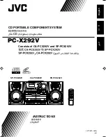
MDS-S38
SERVICE MANUAL
US Model
Canadian Model
AEP Model
UK Model
E Model
Photo: Black
SPECIFICATIONS
MiNi DiSC DECK
9-960-934-12
2004I02-1
© 2004.09
Ver 1.1 2004. 09
Sony Corporation
Audio Group
Published by Sony Engineering Corporaton
Summary of Contents for MINIDISC DECK MDS-S38
Page 8: ... 8 This section is extracted from instruction manual ...
Page 9: ... 9 ...
Page 10: ... 10 ...
Page 11: ... 11 ...
Page 12: ... 12 ...
Page 13: ... 13 ...
Page 14: ... 14 ...
Page 15: ... 15 ...
Page 16: ... 16 ...
Page 17: ... 17 ...
Page 18: ... 18 ...
Page 19: ... 19 ...
Page 20: ... 20 ...
Page 21: ... 21 ...
Page 26: ... 26 3 7 OVER WRITE HEAD 1 Precision screw P1 7x6 2 Over write head ...
Page 38: ......
Page 39: ......
Page 40: ......
Page 41: ......
Page 42: ......
Page 43: ......
Page 44: ......
Page 67: ...MDS S38 MEMO 85 ...