Solid State Logic THE BUS+, User Manual
Introducing the Solid State Logic THE BUS+: a powerful audio mixing console. Get started with ease using our comprehensive Quick Start Manual. To unlock the full potential of this product, download the manual now for free at manualshive.com. Perfectly crafted for your audio mixing needs. Increase your productivity today.
Share
Download


Reviews:
No comments
Related manuals for THE BUS+

D3000
Brand: paasche Pages: 2

SILENT FORCE VAT 264/50
Brand: Villager Pages: 138

TIGER 640
Brand: CAMPAGNOLA Pages: 76

Craftsman 919.176620
Brand: Sears Pages: 20

Mega-Air 2
Brand: DMEGA Pages: 16

901032
Brand: Husky Pages: 85

C3001
Brand: Porter-Cable Pages: 32

S-com plus
Brand: Samson Pages: 9

FC250090L
Brand: Rolair Pages: 47
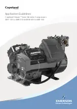
Copeland Stream 4MA-22X
Brand: Emerson Pages: 28

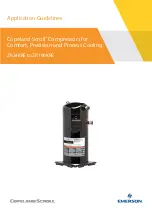
Copeland Scroll ZPD103
Brand: Emerson Pages: 19

Copeland Scroll ZR K3 Series
Brand: Emerson Pages: 18

Copeland Stream Digital 4MAD-22X
Brand: Emerson Pages: 31
Copeland Scroll ZR108KRE
Brand: Emerson Pages: 40

Copeland Scroll ZP23K Series
Brand: Emerson Pages: 24

Copeland Scroll ZR24KRE
Brand: Emerson Pages: 28

Copeland Scroll ZP KC Series
Brand: Emerson Pages: 32

Copeland Scroll ZS KAE Series
Brand: Emerson Pages: 16


