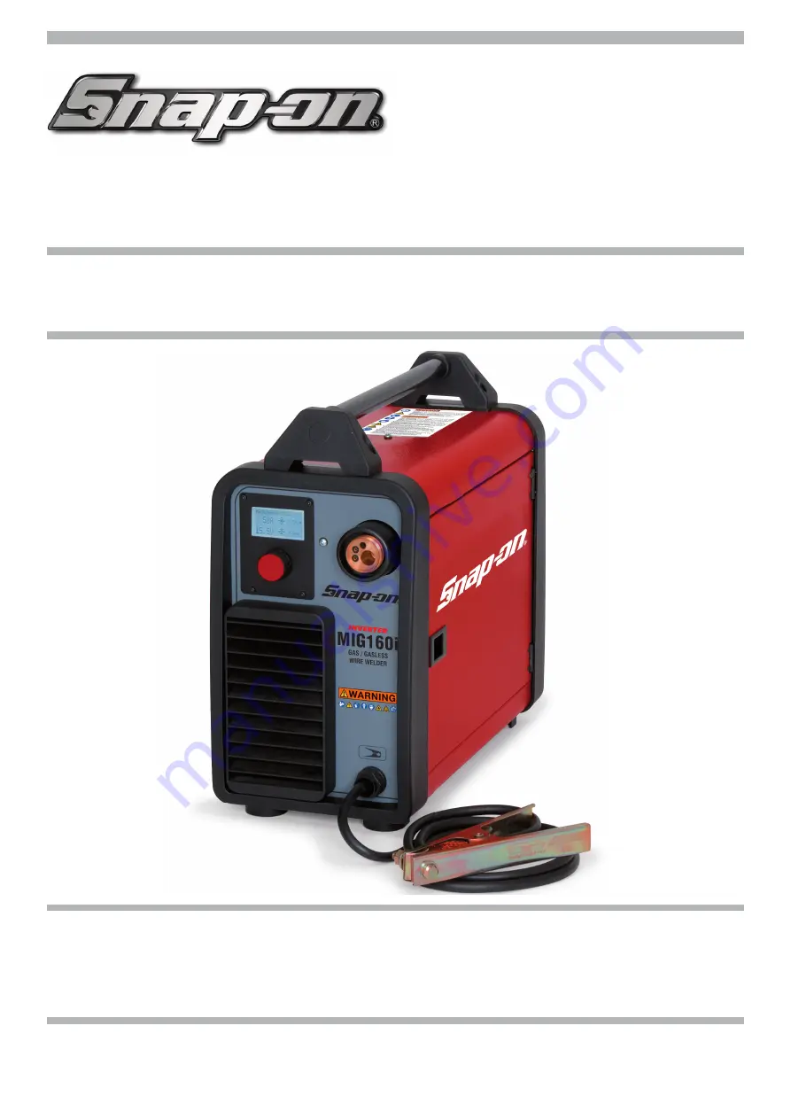
background image

160 AMP MIG WELDER

MIG160i

The MIG160i is a single-phase synergic inverter power source for MIG welding. This versatile 

power source is suitable for various applications from general repairs to specifi c material types 

used in the body shop industry. Welds a variety of material types and thicknesses such as steel, 
stainless-steel, aluminum, high strength and boron steels. Preset synergic curves automatically 
provide proper settings for individual situations and reduce set up times.

INTRODUCTION

form WC 6000

3.300.048/B


INSTRUCTION MANUAL FOR WIRE WELDING MACHINE


Summary of Contents for MIG160i

Page 1: ...al repairs to specific material types used in the body shop industry Welds a variety of material types and thicknesses such as steel stainless steel aluminum high strength and boron steels Preset synergic curves automatically provide proper settings for individual situations and reduce set up times INTRODUCTION form WC 6000 3 300 048 B INSTRUCTION MANUAL FOR WIRE WELDING MACHINE ...

Page 2: ...e of Contents 2 Safety Information 3 4 Specifications 5 Features 6 Description of Equipment 6 Assembling the Unit 7 9 Quick start guide 9 11 Advanced setting 11 12 Maintenance 13 Replacement Parts 14 15 Wiring Diagram 16 Warranty Service and Repair 17 ...

Page 3: ...icon when present gives a graphical description of the potential hazard Arc Welding Electric welding or plasma cutting causes ultra violet rays and weld spatter Bystanders will be exposed to ultraviolet rays and weld spatter Wear welding helmet with appropriate shade lens while using electric welders or plasma cutters Do not allow bystanders while welding or cutting Wear safety shield and protecti...

Page 4: ...de torch lead around your body Do not work next to welding cutting power source Electrical shock and Magnetic fields can cause injury Disposal of Equipment IMPORTANT Disposal of electrical equipment can be hazard ous to the environment Contact local regulations prior to disposal Improper disposal can cause an environmental hazard FUMES AND GASES can be dangerous to your health ITEMS REQUIRED FOR M...

Page 5: ...yed type to be used as a protection for the equipment IP23S Protection rating for the housing Grade 3 as the second digit means that this machine may be stored but it is not suitable for use outdoors in the rain unless it is protected S Suitable for use in high risk environments NOTE The equipment has also been designed for use in environ ments with a pollution rating of 3 See IEC 60664 SPECIFICAT...

Page 6: ...re speed for multiple material thicknesses MIG welding of steel stainless steel and MIG brazing of high strength and Boron steels Welds 5356 and 4047 aluminum with optional torch kit Spot weld and pause features with adjustable on time Adjustable arc length inductance burnback and soft arc starting Faster set up time and reduced production times Over 30 years of industry leading technical support ...

Page 7: ...Disconnect power before servicing Do not remove the grounding lug in any elec trical plug Electrical shock can cause injury During wire installation the welder must be switched off and unplugged to prevent the moving motor roller to move presenting a risk for the operator Install the reel on the support inside the compartment as shown in fig 1 The reel must be installed on the support so the wire ...

Page 8: ...uitable for the aluminum wire you have to weld Install the torch prepared for aluminum PREPARING THE STEEL TORCH FOR WELDING ALUMINUM USING OPTIONAL ALUMINUM KIT MIG 160AK AND OPTIONAL ROLLER CKS 3080942 Remove the metal liner located inside the wel ding torch see figure Insert the carbon teflon liner see figure On the liner protruding from the torch insert the brass mandrel the O ring and the loc...

Page 9: ...ain applications is therefore the car body repair but it can also be used for repairing other galvanized structures within the maximum thickness QUICK START GUIDE 1 TURN ON THE WELDER USING THE ON OFF SWITCH When the machine is switched on for a few moments the display screen A displays the model number of the machine the version and development date of the software and the release number of the s...

Page 10: ...from thin sheet to strutural Fe 035 Steel 100 CO2 023 to 200 All purpose steel welding from thin sheet to strutural Fe 040 Steel 75 Argon 25 CO2 023 to 200 All purpose steel welding from thin sheet to strutural Fe 040 Steel 100 CO2 023 to 200 All purpose steel welding from thin sheet to strutural 308L 030 Stainless Steel 98 Argon 2 CO2 030 to 137 301 302 304 and 305 Stainless Steels 308L 035 Stain...

Page 11: ...ED SETTING Welding Mode Selecting mode 2T the machine starts welding when the torch button is pressed and stops when this is released Selecting mode 4T to start welding press and release the torch button To stop welding press and release again To choose the welding start mode 2T or 4T select one of the 2 modes by means of the knob B and press the knob B for less than 2 seconds to confirm the choic...

Page 12: ...access this function simply highlight it using the knob B and press it for less than 2 seconds The display screen A shows the adjustment bar The figure can be changed and confirmed by pressing the knob B for less than 2 seconds LCD Contrast The adjustment may range from 0 to 100 This function can be used to increase or decrease the brightness of display screen A To access this function simply high...

Page 13: ...make sure the switch F is in O position and that the power supply cable is disconnected from the mains Periodically also clean the inside of the appliance and remove any metal dust using compressed air HOW TO PROCEED AFTER MAKING REPAIRS After making repairs always ensure the wires are fully insulated between the primary side and the secondary side of the machine Avoid the wires coming into contac...

Page 14: ...14 REPLACEMENT PARTS PARTS LIST ...

Page 15: ...M16021 INSIDE BAFFLE 22 CKSM16022 SPACER COIL SUPPORT 23 CKSM16022 SPRING 24 CKSM16022 RING 25 CKSB7116370 FITTING OUTLET 26 CKSM16026 SOLENOID VALVE 27 CKSB7107370 FITTING BARB INLET 28 CKSM16028 BACK PANEL 29 CKSP3010 COVER SWITCH 30 CKSB7129370 SWITCH 31 CKS251069 POWER CORD 32 CKSM16032 MOTOR WITH FAN 33 CKSM16033 SUPPORT 34 CKSM16034 POWER CIRCUIT 35 CKSM16035 COVER 36 CKSM16036 FIXED SIDE PA...

Page 16: ...16 WIRING DIAGRAM ...

Page 17: ...ent of the Equipment by other than Seller s authorized representatives e installation repair or maintenance other than specified operator maintenance of the Equipment or related equipment attachments peripherals or optional features by other than Seller s authorized re presentatives D improper or negligent use application operation care cleaning storage or handling E fire water wind lightning or o...

Page 18: ...torch The liner sJck out should just stop just short of the drive roller 6 Install the enclosed aluminum 035 wire and feed it into the guide tube and then into the torch liner 7 Close the drive arm and be careful that the aluminum wire is aligned in the roller grove Very Important Do not over increase the wire roller tension with the tension knob This will cause the wire to bird nest between the r...

Reviews: