Sounder and Ceiling Beacon
Installation Guide
Part number Product description
SC-33-0120-0001-99
SC-33-0220-0001-99
SmartCell RED Sounder and Ceiling Beacon
(VAD White Flash)
SmartCell WHITE Sounder and Ceiling
Beacon (VAD White Flash)
1
Pre installation
Sounder and ceiling beacon
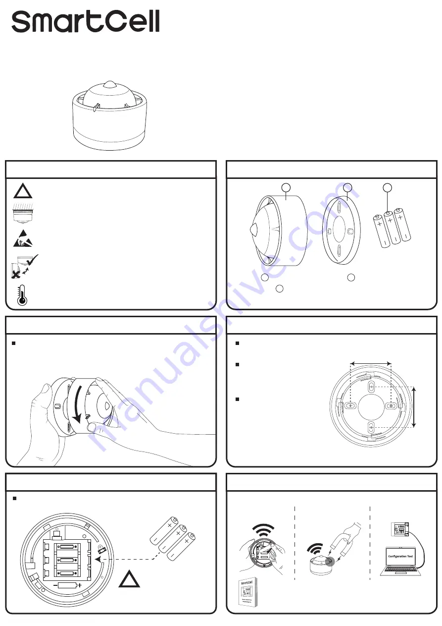
2 Components
Mounting plate
2
1
!
Installation must conform to applicable local installation codes and
should only be installed by a fully trained competent person.
This device contains electronics that may be susceptible to damage
from Electrostatic Discharge (ESD). Take appropriate precautions
when handling electronic boards.
The use of a non-metallic spacer should be considered if mounting
the device on to a metal surface.
This device is suitable for ceiling mounting only. Wall mounted
variants are also available.
*When batteries are not supplied, only fit specified batteries.
Batteries
(not included in some regions*)
3
5 Fit batteries
When fitting / replacing batteries, observe correct polarity, using only
specified batteries.
6 Configuration
ER14500
AA
ER14500
AA
+
-
+
-
ER14500
AA
+
-
Refer to the programming manual (TSD155) for full programming
details.
The device must now be added (programmed) to the control panel.
Device powering
Method 1
Magnet application
Method 2
Via computer
Method 3
4 Fix mounting plate
When fixing to the ceiling, all four fixing positions should be used to
ensure a firm fixing.
Use suitable fasteners and
fixings.
60 mm
60 mm
Where existing electrical
mounting boxes are present,
two fixing positions may be
used.
3 Remove mounting plate
Remove the mounting plate by turning the device ANTICLOCKWISE, to
release it from the mounting plate.
OBSERVE BATTERY
POLARITY!
!
3x ER14505M
LITHIUM 3.6V
©2019 EMS Ltd. All rights reserved. Page 1 of 2
TSD108-0001-99 (Issue 1) 26/09/2019 AJM
2
1
3
To ensure correct operation, products must be used within the
specified environmental operating conditions.


