SLE AEDI WASH GLOBUS 16 MC, User Manual
Looking for a comprehensive User Manual for the high-performance SLE AEDI WASH GLOBUS 16 MC? Look no further! Download our detailed manual for free at manualshive.com, providing all the essential instructions you need to optimize your experience with this exceptional product.
Share
Download


Reviews:
No comments
Related manuals for AEDI WASH GLOBUS 16 MC

NE-1
Brand: Ocean Optics Pages: 6

Light from another world
Brand: Occhio Pages: 74
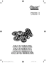
50717
Brand: Oase Pages: 36

Ciel JYL7503A
Brand: JONATHAN Y Pages: 2

KESWICK HDP15307
Brand: HAMPTON BAY Pages: 8

EDGEHILL HDP06587BL
Brand: HAMPTON BAY Pages: 8

Trimming Traditions 30 IN ICY RACCOON
Brand: Sears Pages: 2

SORA-3
Brand: Lightolier Pages: 2

LT-1220
Brand: Jolly Pages: 22

olivia mini
Brand: Zafferano Pages: 8
CA-350 50AP
Brand: Pahlen Pages: 58

Pier 60
Brand: LBL Pages: 4

460LED BSW
Brand: Uplus Lighting Pages: 12

Vi. F
Brand: Catellani & Smith Pages: 8

HANSANDFRANZ KYUDO
Brand: KUNDALINI Pages: 8

Calculite C6AD
Brand: Lightolier Pages: 2

NINEBYFOUR
Brand: Waarmakers Pages: 12

2CLED
Brand: Seto Pages: 12


