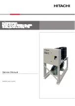
background image

TME-N ActiveCore

SKOPE Top Mount Chiller
Hydrocarbon 
 

Service Manual

MAN80128 R

ev

. 1.0 Nov.

 2018

Summary of Contents for TME-N ActiveCore

Page 1: ...TME N ActiveCore SKOPE Top Mount Chiller Hydrocarbon Service Manual MAN80128 Rev 1 0 Nov 2018...

Page 2: ...skope co nz Trademark Infringement The SKOPE trademark on this product is infringed if the owner for the time being does any of the following Applies the trade mark to the product after their state co...

Page 3: ...18 Main Assembly TME1000N A Series 19 Cabinet Assembly TME650N A Series 20 Cabinet Assembly TME1000N A Series 21 Glass Door Assembly 22 Lit Sign Assembly 23 Unit Assembly UTHCNI 0010 24 6 Installatio...

Page 4: ...or 47 Compressor Electrics 47 Refrigeration System 48 Unit Removal 48 Diagnostics 48 Electronic Controller 49 Controller Location 49 QC Terminals 49 Replacing the Controller 50 Door Switch 51 Control...

Page 5: ...environmental impact Special service requirements are needed as hydrocarbon is a flammable refrigerant Safety hazards The main hydrocarbon safety hazards are Flammable refrigerant Venting of hydrocarb...

Page 6: ...UST Not perform any Hot Work brazing etc in the field These are to be completed in a SKOPE approved hydrocarbon workshop in a dedicated specific Hazardous Work Area for Hot Work x MUST Not transport a...

Page 7: ...KOPE TME ActiveCore top mount chillers detailed in the table below Refer to the relevant product specification sheet available on the SKOPE website www skope com for specifications Series Model SKOPE...

Page 8: ...s information on data logging alarm notification and diagnostic control See SCS Connect Field App and Track App on page 11 for information on setting up and using the app SCS Connect Track App The SCS...

Page 9: ...temperature However they may be very close depending on how the controller is set to sense temperature 3 Light Switch Night Mode back abort Button Press to switch the lights on or off Press and hold...

Page 10: ...tings are suspected reload the complete parameter set Reset Returns the controller back to factory settings Parameter set must be reloaded after performing a reset Manual test Allows inspection of inp...

Page 11: ...te you must define a 4 digit PIN code This can be any code unique to you Each time you start the app you will be required to enter this same PIN code This is to prevent other people accessing the app...

Page 12: ...rameters are changed unless absolutely necessary If incorrect parameter settings are suspected reload the complete parameter set Note Updated parameters are not applied until DISCONNECT has been selec...

Page 13: ...abinet has temporarily shut down to prevent damage and will restart once the supply voltage decreases 1 2 3 4 should be a one off if continues line voltage rural voltage setting parameter controller U...

Page 14: ...current protection activated The compressor was drawing too much current and has shut down to prevent permanent damage 2 3 4 Take spare unit in case refrigeration system fault condenser blocked poor i...

Page 15: ...out The compressor cut out on its internal protection or pressure switch 2 3 4 Take spare unit in case refrigeration system fault condenser blocked poor installation ventilation cabinet seal leaking d...

Page 16: ...oor cabinet GNS indicates a Green sleeve on the wire LED Power Supply N L S25 P25 S5 1 P5 1 LED Lighting WIRE COLOURS BK Black BN Brown RD Red OG Orange GN Green BU Blue GY Grey WH White GNYE Green Ye...

Page 17: ...17 SKOPE TME N ActiveCore Wiring Service Manual Notes...

Page 18: ...OPE TME N ActiveCore 5 Spare Parts Main Assembly TME650N A Series Parts Main Assembly TME650N Series No Description Page 1 Cabinet assembly Page 20 2 Door assembly Page 22 3 Sign assembly Page 23 4 Un...

Page 19: ...pare Parts Service Manual Main Assembly TME1000N A Series Parts Main Assembly TME1000N Series No Description Page 1 Cabinet assembly Page 21 2 Door assembly Page 22 3 Sign assembly Page 23 4 Unit asse...

Page 20: ...ack 1 Top hinge RH HB0070110582A 2 Door lock bracket cabinet piece HB0070206938 3 Bottom hinge RH HB0070110851 4 Tension bracket HB0070110580 5 Height adjustment block lock nut HB0070110581 6 Controll...

Page 21: ...ock bracket cabinet piece HB0070206938 4 Bottom hinge LH HB0070110850 5 Bottom hinge RH HB0070110851 6 Tension bracket HB0070110580 7 Height adjustment block HB0070110581 8 Controller clip HB007020633...

Page 22: ...Colour Black 1 TME650N door assembly RH HB0070832242 TME1000N door assembly RH HB0070832243 TME1000N door assembly LH HB0070832244 2 Door lock bracket door piece TBC 3 Bush PLM5075 4 Door handle HAN1...

Page 23: ...0825987 2 Sign back strip HB0070110813 3 Sign side HB0070206332 4 Sign light bar lit sign ELL11772 5 Controller surround HB0070206332 6 Sign panel opal lit sign PLY11242 MT65 7 Sign panel transparent...

Page 24: ...24 Spare Parts Service Manual SKOPE TME N ActiveCore Unit Assembly UTHCNI 0010 1 26 27 28 8 30 22 29 31 2 21 5 7 32 6 4 25 23 24 20 9 18 11 17 19 14 16 13 10 15 12 1 2 3...

Page 25: ...mperature probe HB0070401693B 14 Condenser fan blade HB0074000313 15 W Drive SCS Connect electronic controller ELZ11749 16 Controller box base HB0070206125 17 Unit electrics box enclosure front HB0070...

Page 26: ...close properly Sunlight Do not install the chiller in direct sunlight Uneven Surface Do not install the chiller on an uneven surface Surface The installation surface must be capable of supporting the...

Page 27: ...s at each end of the handle Ensure that the spring clips point up 3 Locate BOTH handle mounts simultaneously onto both door brackets Then push the handle down onto the brackets until the handle locks...

Page 28: ...rough the holes on the inside of the door frame top and bottom screws only and remove the handle 3 Remove the bracket s from the handle mount by pressing the bracket in and down until it unclips from...

Page 29: ...standard shelves unload and remove the shelf establish the desired position and slide the shelf clip in each of the shelf support strips to the desired position see To adjust the shelf clip height on...

Page 30: ...ated in the cabinet electrics panel above the door s via the wiring loom s which run down the sidelight channel Lighting components are all non serviceable items If a component is faulty it should be...

Page 31: ...nd clean plugs on top of the cabinet Light power supply fault Replace light power supply Light component not working Plug not connected properly Check and clean plug connection in side light channel b...

Page 32: ...power supply and reassemble 1 Disconnect the chiller from the power supply 2 Unplug the light from the wire loom 3 Gain access to the cabinet electrics panel see procedure above 4 Move up to the cabi...

Page 33: ...top of the sign 5 Remove additional sign panel by sliding up and out of the sign 6 Cut the cable tie holding the light cable at the back of the sign 7 Undo the two most RH sign reflector screws 8 Car...

Page 34: ...he perimeter of the door Remove the gasket by peeling it from the door frame starting at a corner If the gasket is out of shape after refitting use a hair dryer to heat and reshape it Removing and Ref...

Page 35: ...e to the top of the door and partially fix in place on the top of the cabinet Align the door with the cabinet and tighten the fixing screws Ensure the top hinge spacer is fitted under the top hinge be...

Page 36: ...e to rotate 180 to provide tension While holding door tension on the capstan fit the tension bracket to the top screw hole so that it supports the door tension on the capstan Outside door pictured 4 F...

Page 37: ...tom hinge 6 Remove the door lock bracket from the door and fit to the opposite end 7 Remove the bush and retain for the other end of the door 8 Remove the capstan bush and bush washer and unhook from...

Page 38: ...is suspected the system must not be opened it must be sent to a SKOPE approved service depot for repair Safety hazards The main hydrocarbon safety hazards are Flammable refrigerant Venting of hydrocar...

Page 39: ...pliant cabinet Refer to the cabinet rating label to determine if the cabinet is suitable for use with a hydrocarbon unit The rating label MUST state refrigerant as R290 If the label states a different...

Page 40: ...line piercing valves suitable for 6mm tube Service vehicle Suitable for transporting flammable gas being HC refrigeration systems Vehicle storage area must be well ventilated externally and not venti...

Page 41: ...n 3 Detach the electronic controller assembly from the top of the cabinet and clip it onto the top of the unit 4 Remove electrics cover and unplug the mains supply plug and cabinet plugs Note The unit...

Page 42: ...nt refrigeration unit retain these parts for use on the new spare part replacement unit The evaporator tub lid top strap brackets and hold down brackets can be ordered in addition to the refrigeration...

Page 43: ...tions Take care when refitting to ensure all plugs are securely attached to the correct sockets To remove and open the unit electrics box assembly UPDATE 1 Disconnect the chiller from the power supply...

Page 44: ...0 7 10 11 12 6 19 17 2 3 Key Colour Description Key Colour Description 1 n a Not used 11 n a Not used 2 White Controller Signal 12 n a Not used 3 Blue Controller Return 13 n a Not used 4 Black Trace H...

Page 45: ...4 Cut the cable ties holding the cables along the unit and free up the condenser fan motor cable 5 Remove the fan assembly fan motor fan blade mounting brackets from the unit by lifting the shroud up...

Page 46: ...or manufacturer recommended torque settings shown in the table below Fan motor manufacturer recommended torque settings To access the evaporator fan assembly To replace the fan blade IMPORTANT Replace...

Page 47: ...are located on the front of the compressor To access the compressor electrics remove the refrigeration unit see page 41 and unit cover see page 44 The capacitor unclips from the relay cover and the re...

Page 48: ...minutes until the evaporator temperature stabilises 4 Refer to the table below to determine if the system charge is correct A system with the correct refrigerant charge will frost back towards the co...

Page 49: ...at the back of the controller are locking QC terminals which cannot be pulled off without pressing in the locking tabs Use needle nose pliers to unlock and gently remove the terminals 1 Disconnect th...

Page 50: ...uired and reconnect to the power supply 5 Use a mobile device to connect to the controller with the SCS Connect Field app see SCS Connect Field App and Track App on page 11 6 Navigate to the LOAD PARA...

Page 51: ...ller from the power supply 2 Disconnect the door switch cable plug from the inline connector on top of the cabinet 3 Unscrew the two fixing screws from the door switch and remove 4 Fit the replacement...

Page 52: ...s and cables on the evaporator tub perimeter 5 Carefully lift the coil up and out of the evaporator tub Take care of pipes and cables when lifting out 6 Detach the probe from the side of the evaporato...

Page 53: ...unit cover see page 44 3 Detach the probe from the side of the condenser coil and trace the probe cable back to the unit electrics box cutting cable ties as required and unplug see page 42 4 Following...

Page 54: ...see page 30 2 Remove the sign panel 3 Detach the refrigeration unit and carefully push back or remove to allow access to the cabinet electrics cover 4 Unscrew the cabinet electrics cover 5 Detach the...

Page 55: ...months The condenser coil must be kept clean for efficient and reliable operation To clean the condenser coil and optional condenser filter WARNING Unplug the chiller from the power supply before clea...

Page 56: ...ode Switch the light on while keeping the chiller in night mode by pressing the light button on the electronic controller faceplate Change the chiller into day mode by pressing and holding the Day Nig...

Page 57: ...heat load Ensure the cabinet has good ventilation around the refrigeration unit Ensure the cabinet is within the maximum operating conditions Set point is to high Lower set point Moisture build up on...

Page 58: ...door and check for gas inside cabinet Is gas detected Connect cabinet to power supply Tag power supply with Out of Service warning label Refrigeration system is considered to have a gas leak Check ref...

Page 59: ...or drains Fit HC gauge set Safely release gas do NOT release gas into water After gas is released remove gauges and fit caps to valves Ensure valves not leaking Send faulty unit for repair The unit m...

Page 60: ...SKOPE Contacts SKOPE Industries Limited A B N 73 374 418 306 AU 1800 121 535 NZ 0800 947 5673 skope skope com www skope com...

Reviews: