background image

Rev. 0.2 9/06

Copyright © 2006 by Silicon Laboratories

C8051F34x-DK

C8051F34x-DK

C8051F34

X

 D

E V E L O P M E N T

 K

I T

 U

S E R

S

 G

U I D E

1.  Kit Contents

The C8051F34x Development Kit contains the following items:

• C8051F340 Target Board
• C8051Fxxx Development Kit Quick-start Guide
• Silicon Laboratories IDE and Product Information CD-ROM. CD content includes:

• Silicon Laboratories Integrated Development Environment (IDE)
• Keil 8051 Development Tools (macro assembler, linker, evaluation ‘C’ compiler)
• Source code examples and register definition files
• Documentation
• C8051F34x Development Kit User’s Guide (this document)

• AC to DC Power Adapter
• USB Debug Adapter (USB to Debug Interface)
• USB Cable

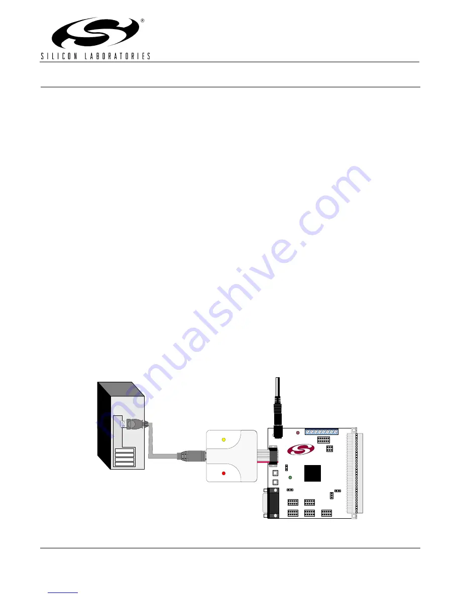
2.  Hardware Setup using a USB Debug Adapter

The target board is connected to a PC running the Silicon Laboratories IDE via the USB Debug Adapter as shown
in Figure 1.

1. Connect the USB Debug Adapter to the DEBUG connector on the target board with the 10-pin ribbon cable.
2. Connect one end of the USB cable to the USB connector on the USB Debug Adapter. 
3. Connect the other end of the USB cable to a USB Port on the PC.
4. Connect the ac/dc power adapter to power jack P1 on the target board.

Notes:

• Use the Reset button in the IDE to reset the target when connected using a USB Debug Adapter.
• Remove power from the target board before removing the ribbon cable from the target board. Connecting or 

disconnecting the cable when the devices have power can damage the device and/or the USB Debug 
Adapter.

Figure 1. Hardware Setup using a USB Debug Adapter

PC

USB 

Cable

USB Debug Adapter

AC/DC

Adapter

Target Board

SILICON LABORATORIES

PWR

P1.6

P3.

7

RE

S

E

T

Port 4

Port 3

Port 1

Port 2

Port 0

MCU

S

ili

con
 La
bo

ra

to

ries

U

SB D

EBU

G AD

APTE

R

Run

Sto
p

Po
w

e

r

Downloaded from 

Elcodis.com


electronic components distributor


Summary of Contents for C8051F34-DK Series

Page 1: ... via the USB Debug Adapter as shown in Figure 1 1 Connect the USB Debug Adapter to the DEBUG connector on the target board with the 10 pin ribbon cable 2 Connect one end of the USB cable to the USB connector on the USB Debug Adapter 3 Connect the other end of the USB cable to a USB Port on the PC 4 Connect the ac dc power adapter to power jack P1 on the target board Notes Use the Reset button in t...

Page 2: ...ng IDE installation The evaluation version of the C51 compiler is the same as the full professional version except code size is limited to 4 kB and the floating point library is not included The C51 compiler reference manual can be found under the Help menu in the IDE or in the SiLabs MCU hlp directory C51 pdf 4 4 Using the Keil Software 8051 Tools with the Silicon Laboratories IDE To perform sour...

Page 3: ...oolbar or selecting Project Build Make Project from the menu Note After the project has been built the first time the Build Make Project command will only build the files that have been changed since the previous build To rebuild all files and project dependencies click on the Rebuild All button in the toolbar or select Project Rebuild All from the menu 2 Before connecting to the target device sev...

Page 4: ...r with a timer 5 3 Universal Serial Bus USB Application Example The included USB application example requires Windows 98SE 2000 XP operating system This example consists of three parts firmware running on the C8051F340 device a USB device driver running on the host PC and a host application The host application communicates with the C8051F340 via USB allowing the user to view and to change the sta...

Page 5: ...the Next button 3 Select Search for a suitable driver for my device recommended and press the Next button 4 Select Specify a location under Optional search locations and press the Next button 5 Press the Browse button to locate the SiLabsInt inf driver installation file located by default in the SiLabs MCU Examples C8051F34x C USB_INT directory Once this file is selected press the OK button 6 Veri...

Page 6: ...der J6Port 4 header J7Connects the 3V supply net to the VDD supply net J8USB Power or VDD power selection header J9Debug connector for debug adapter interface J10 J11External crystal enable connectors J12Port I O jumper configuration block J1396 pin female connector J15Jumper connection for pin 1 5 to capacitors used when VREF is internally generated J16Jumper connection for potentiometer source t...

Page 7: ...purpose I O GPIO pins through headers Pressing P2 0 or P2 1 generates a logic low signal on the port pin Remove the shorting blocks from the J12 header to disconnect Switch P2 0 and Switch P2 1 from the port pins The port pin signals are also routed to pins on the J1 I O connector See Table 1 for the port pins and headers corresponding to each switch Three LEDs are also provided on the target boar...

Page 8: ...340 target board can be configured as a self powered USB device to take power from the USB cable instead of the ac dc adapter connected at P1 To configure the target boards as a self powered USB device short the VREGIN and VBUS pins on the J8 header Note When the C8051F340 target board is self powered from the USB the Serial Adapter is not powered from the target board The Serial Adapter must be p...

Page 9: ...l shorting block to connect UART0 CTS P2 7 to transceiver 6 8 Analog I O P2 Several of the C8051F340 target device s port pins are connected to the P2 terminal block Refer to Table 5 for the P2 terminal block connections 6 9 USB Debug Adapter Target Board Power Connector J19 The USB Debug Adapter includes a connection to provide power to the target board This connection is routed from J9 10 to J19...

Page 10: ...C8051F34x DK 10 Rev 0 2 7 Schematics Figure 3 C8051F340 Target Board Schematic Page 1 of 2 Downloaded from Elcodis com electronic components distributor ...

Page 11: ...C8051F34x DK Rev 0 2 11 Figure 4 C8051F340 Target Board Schematic Page 2 of 2 Downloaded from Elcodis com electronic components distributor ...

Page 12: ...ts Removed Section 2 Hardware Setup using an EC2 Serial Adapter See RS232 Serial Adapter EC2 User s Guide Removed Section 8 EC2 Serial Adapter See RS232 Serial Adapter EC2 User s Guide Removed Section 9 USB Debug Adapter See USB Debug Adapter User s Guide Downloaded from Elcodis com electronic components distributor ...

Page 13: ...C8051F34x DK Rev 0 2 13 NOTES Downloaded from Elcodis com electronic components distributor ...

Page 14: ...bed features or parameters Silicon Laboratories reserves the right to make changes without further notice Silicon Laboratories makes no warranty rep resentation or guarantee regarding the suitability of its products for any particular purpose nor does Silicon Laboratories assume any liability arising out of the application or use of any product or circuit and specifically disclaims any and all lia...

Reviews: