Siemens Synco RMK770, Basic Documentation
The Siemens Synco RMK770 is a versatile building automation system that ensures optimal control and energy efficiency. With its user-friendly interface and advanced features, this device offers endless possibilities. Enhance your understanding of its capabilities with our free basic documentation manual, available for download at manualshive.com.
Share
Download


Reviews:
No comments
Related manuals for Synco RMK770

Sensedge
Brand: Kaiterra Pages: 12

S70
Brand: Nevo Pages: 4

HAS-QN0
Brand: Honeywell Pages: 16
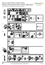
FRIEDLAND FGGA01 Series
Brand: Honeywell Pages: 2

Tuxedo
Brand: Honeywell Pages: 48

Tuxedo Touch
Brand: Honeywell Pages: 64

MS4209F
Brand: Honeywell Pages: 2

RolloTron Basic 1100
Brand: RADEMACHER Pages: 84

EFHRFR 001
Brand: Watts Pages: 2

DWF-200M
Brand: Daewoo Pages: 16

YS6704-UC
Brand: Yolink Pages: 34

WIFIP121EWT
Brand: nedis Pages: 52

01422
Brand: Vimar Pages: 6

Elvox 805N
Brand: Vimar Pages: 8

TZ67-E
Brand: TKB Home Pages: 5

Deco X20
Brand: TP-Link Pages: 24

Kizbox II
Brand: Overkiz Pages: 8

WHLRR
Brand: Overkiz Pages: 48


