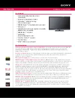
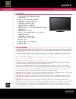
Summary of Contents for SIMATIC HMI TP 070

Page 1: ...ng the TP 070 4 Operation of Screen Objects 5 System Settings 6 Communication 7 Installation 8 Unit Description 9 Maintenance Upkeep 10 Operating System Update 11 Appendices A D Glossary Index Release 03 00 6AV6591 1DC01 1AB0 Touch Panel TP 070 Equipment Manual SIMATIC HMI ...

Page 2: ...l operation and maintenance Trademarks The registered trademarks of Siemens AG are listed in the Preface Some of the other designations used in these documents are also registered trademarks the owner s rights may be violated if they are used be third parties for their own purposes Impressum Editor and Publisher A D PT1 Safety Guidelines This manual contains notices which you should observe to ens...

Page 3: ...IMATIC HMI documentation is provided in appendix D Organization of the manual The TP 070 equipment manual is organized into the following chapters Chapter Contents 1 2 Overview of features and functional scope of the TP 070 3 7 Commissioning operation system settings and communication 8 10 Mechanical and electrical installation unit description as well as maintenance and upkeep of the TP 070 11 In...

Page 4: ...eases of this manual correspond to the following versions of the STEP 7 Micro WIN 32 and STEP 7 Micro WIN 32 Toolbox configuration software Release Comment Micro WIN 32 version Micro WIN 32 Toolbox version 03 00 First release of the TP 070 equipment manual From Version 3 1 From Version 1 0 Trademarks The following names are registered trademarks of the Siemens AG S SIMATICR S SIMATIC HMIR S HMIR S...

Page 5: ...e Local time Mo Fr 7 00 to 17 00 Local time Mo Fr 8 00 to 19 00 Local time Mo Fr 8 30 to 17 30 Telephone 49 911 895 7000 Telephone 1 423 461 2522 Telephone 65740 7000 Fax 49 911 895 7002 Fax 1 423 461 2231 Fax 65740 7001 E Mail simatic support nbgm siemens de E Mail simatic hotline sea siemens com E Mail simatic hotline sae siemens com sg SIMATIC Premium Hotline charged only with SIMATIC Card Time...

Page 6: ...der http www ad siemens de support html 00 Abbreviations The abbreviations used in this equipment manual have the following meaning CCFL Cold Cathode Fluorescence Lamp CPU Central Processing Unit ESD Electrostatic Sensitive Device HMI Human Machine Interface IF Interface LCD Liquid Crystal Display MPI Multipoint Interface SIMATIC S7 PC Personal Computer PLC Programmable Logic Control PPI Point to ...

Page 7: ...w of Screen Objects 5 2 5 2 Status Button 5 3 6 System Settings 6 1 6 1 Setting an Operating Mode 6 2 6 2 Screen Settings 6 3 6 3 Deactivate Screen 6 5 7 Communication Management for SIMATIC S7 7 1 7 1 Basic Methods of Functioning 7 2 7 2 Connection to S7 200 via MPI 7 3 7 3 Optimization 7 6 8 Installation 8 1 8 1 Mechanical Installation 8 2 8 2 Electrical Installation 8 4 8 2 1 Connect configurat...

Page 8: ... vi TP 070 Equipment Manual Release03 00 10 Maintenance Upkeep 10 1 11 Operating System Update 11 1 Appendix A Technical Data A 1 B Interface Assignment B 1 C ESD Guidelines C 1 D SIMATIC HMI Documentation D 1 ...

Page 9: ...ration and monitoring It provides a realistic representation of the machine or system to be monitored Its area of use includes implementation in machine and apparatus construction as well as in the packing and electronics industry The high degree of protection IP65 on the front side and non implementation of moving storage media such as hard disks and floppy disks ensure the TP 070 is also suitabl...

Page 10: ... the respective process requirements by using the STEP 7 Micro WIN 32 from version 3 1 and STEP 7 Micro WIN 32 Toolbox from version 1 0 configuration software The TP 070 can be used to control and monitor the process intuitively Setpoint values or control element settings for instance can be modified by entering values or touching configured buttons display processes machines and systems graphical...

Page 11: ...ownload the project to the operating unit refer to Configuration phase in figure 1 1 Once the project has been successfully downloaded connect the operating unit to the PLC The operating unit can then communicate with the PLC and respond according to the information configured for running the program in the PLC refer to Process control phase in figure 1 1 Create project data Store project data Dow...

Page 12: ...lue mode Active screen area B H in mm 116 87 5 7 Resolution pixels 320 240 Monochrome 4 level Back lighting CCFL tube Half Brightness Life1 approx h 50 000 1 Refer to the Glossary for a definition Further information Detailed information on the technical data of the operating unit is provided in appendix A of this manual Information concerning configuration of the operating unit is provided in the...

Page 13: ...ues quoted are the maximum values which can be managed by the operating unit The values are limited by the size of the memory used Function Comment Screens View 4 Screen objects Output field Input field Text Graphics State button Bar Screen settings Contrast 4 Touch calibration 4 Communication SIMATIC S7 200 MPI to 19 2 kbits s 4 2 ...

Page 14: ...Functionality 2 2 TP 070 Equipment Manual Release03 00 ...

Page 15: ...t Manual Release03 00 Commissioning In this chapter This chapter provides information on starting up the operating unit for the first time page 3 2 restarting the operating unit page 3 3 testing a configuration page 3 3 3 ...

Page 16: ...he operating unit which is necessary to put the unit into service Step Procedure 1 Connect the operating unit interface IF1B RS485 to the configuration computer using a PC PPI cable 2 Switch on the power supply for the operating unit Since no configuration has been loaded at this point the operating unit automatically switches to Download mode The operating unit displays the message Connecting to ...

Page 17: ...phase Step Procedure 1 Connect the operating unit interface IF1B RS485 to the configuration computer using a PC PPI cable 2 Switch on the power supply for the operating unit 3 During the operating unit start up phase a menu appears briefly on the screen Touch the Download button to set the operating unit to Download mode before it is initialized The operating unit displays the message Connecting t...

Page 18: ...Commissioning 3 4 TP 070 Equipment Manual Release03 00 ...

Page 19: ...ing the TP 070 In this chapter This chapter contains information on how to operate touch elements from page 4 2 enter values from page 4 4 operate screens page 4 6 Information regarding operation for special screen objects is provided in chapter 5 4 ...

Page 20: ...ouch elements are contact sensitive operating elements provided on the touch panel screen such as buttons and input fields Their operation is basically no different from pressing conventional keys Touch elements are operated by touching them lightly with your finger or a suitable object Note Never use pointed or sharp instruments to operate the Touch Panel to prevent damage to the plastic surface ...

Page 21: ...the required action actually having been executed The type of visual acknowledgement is dependent on the operating element touched Buttons In the case of 3D effect configurations visual representation is distinguished according to the statuses touched and untouched Examples of representation are illustrated below by means of the Status button Untouched Touched Input fields After an input field has...

Page 22: ...lid the new value is accepted in the input field If the entry is not valid the new value is rejected and the old one reset System keyboard The buttons available for operation on the system keyboard are dependent on the type of value to be entered Buttons which are available for operation are highlighted and those not available appear simply as empty areas Figure 4 1 illustrates an example of the s...

Page 23: ... to the left Move current input position one character to the left Move input position to the right Move current input position one character to the right Cancel Escape Discard input and close the system keyboard Delete character Delete the character to the left of the input position Enter Confirm input and close the system keyboard Enter value Characters entered are aligned to the right On enteri...

Page 24: ...amic do not refer to the possibility of dynamically positioning screen partitions but to the connection to the PLC Static partitions e g text and graphics are not updated by the PLC Dynamic partitions e g input and output fields and bars can be linked to the PLC and display current values constantly read in from the PLC memory Their connection to the PLC is established by means of tags Screen obje...

Page 25: ...f Screen Objects In this chapter This chapter introduces the screen objects which may be contained in a configuration and explains their operation It provides the following information a summary of screen objects page 5 2 the state button from page 5 3 5 ...

Page 26: ...ements for example Text can be configured over several lines and cannot be altered on the operating unit Graphics Graphics can be used in the configuration e g to represent a system or as an illustrative symbol for configured display and operating elements State button A state button is a display and input element with two different statuses Notes on the statu buttons is provided on page 5 3 Bar B...

Page 27: ... be used to define text or graphics for the two statuses ON and OFF Option key The state button reacts as a key in button When pressed the state button changes to the status ON It remains in this status as long as the state button is pressed When released it automatically switches back to OFF Event related initiation Use the configuration software to assign the state button one or more functions a...

Page 28: ...to switch the configuration software can be used to assign different text or graphics to indicate the status of the button during runtime Figure 5 1 illustrates an example of a state button when pressed left and not pressed right Figure 5 1 The two statuses relate to the state button when the switch option is set ...

Page 29: ...stem Settings In this chapter This chapter provides information on the following general settings which can be modified on the operating unit online Operating mode page 6 2 Screen contrast and calibration page 6 3 Screen deactivation page 6 5 6 ...

Page 30: ...In this mode there is no logical connection between the operating unit and PLC The operating unit can be operated but processes cannot be operated or visualized Online mode When using this mode processes can be operated and visualized without restriction There is a logical connection between the operating unit and PLC or the operating unit attempts to establish one Online mode is the predefined op...

Page 31: ... phase Step Action 1 Switch on the power supply for the operating unit 2 During the initialization phase the menu illustrated in figure 6 1 appears briefly Touch the Config button to call in the configuration menu displayed in figure 6 2 3 Touch the Contrast and Contrast buttons to change the contrast setting of the screen Note Touch the buttons sufficiently long enough to detect contrast changes ...

Page 32: ...e operating unit it starts it up automatically after 10 seconds The configuration can be started manually by touching the Start button Change screen settings during operation The screen settings can also be changed while the system is actually running A condition for this is that the following functions are linked to operating elements in the actual project Change contrast Touch calibration Save s...

Page 33: ...er to deactivate the screen on the operating unit the function Clean Screen must have been assigned to a button in the project After touching the relevant button the screen is cleared and a bar graph appears The screen is then deactivated for the time Deactivation time defined in the configuration default setting 30 seconds The TP 070 can then be cleaned without any functions being triggered inadv...

Page 34: ...System Settings 6 6 TP 070 Equipment Manual Release03 00 ...

Page 35: ...the TP 070 to the CPU of the SIMATIC S7 200 concerns a point to point connection with the protocol profile DP T Installation The driver for connecting the SIMATIC S7 200 is supplied with the configuration software and installed automatically Connection of the TP 070 to the SIMATIC S7 200 is basically restricted to the physical connection of the operating unit Special function blocks for connection...

Page 36: ...mmunication structure Task of the tags The general exchange of data between the SIMATIC S7 200 and TP 070 is performed via the process values To do this tags must be specified in the configuration which point to an address in the S7 The TP 070 reads the value from the specified address and displays it In the same way the operator can enter a value on the operating unit which is then written to the...

Page 37: ...oad the S7 program must not be used for the connection between the operating unit and S7 200 The maximum baud rate is 19 2 kbits s Operating unit configuration In order that the TP 070 can communicate with a CPU and exchange data the TP 070 must be correspondingly configured To do this the TP 070 address must be defined in the configuration with STEP 7 Micro WIN and the connections to the communic...

Page 38: ...S7 module CPU to which the TP 070 is connected HSA Highest Station Address this must be identical throughout the whole network configuration Data types supported The data types listed in table 7 2 are available for the configuration of tags Table 7 2 Data types available Data types supported for S7 200 Data type Addressed by Format Tag V BYTE INT WORD DINT DWORD REAL BOOL STRING Input I BYTE INT W...

Page 39: ... unnecessarily impairs overall performance Set the acquisition cycle to correspond to the modification time of the process values The rate of change of temperature of a furnace for example is considerably slower than the acceleration curve of an electric motor Guideline value for the acquisition cycle Approx 1 second In order that changes on the PLC are reliably detected by the TP 070 they must oc...

Page 40: ...Communication Management for SIMATIC S7 7 6 TP 070 Equipment Manual Release03 00 ...

Page 41: ...lease03 00 Installation In this chapter This chapter provides information on Installation of the operating unit from page 8 2 Electrical connections to the power supply page 8 5 the configuration computer page 8 7 the PLC page 8 8 8 ...

Page 42: ...e ensured when the seal on the front plate of the operating unit is fitted correctly Caution S The unit must be brought to room temperature before it is commissioned If condensation forms do not switch the unit on until it absolutely dry S To prevent the operating unit overheating during operation the angle of inclination from vertical installation may not exceed a maximum of 35_ do not expose the...

Page 43: ...been secured 2 Insert the hooks of the screw type clamps enclosed in the corresponding recesses in the housing of the operating unit The individual positions are indicated in the figure by means of arrows Front panel Operating unit 3 Use a screwdriver to tighten the operating unit from the rear in the front panel Note Make sure the seal is seated correctly against the front panel Never apply torqu...

Page 44: ...ation A precondition for error free operation is an EMC compatible hardware design of the PLC and the use of interference proof cables The guidelines on interference free design of the PLCs apply equally to installation of the operating unit Caution Only shielded cables are permitted for all signal connections Screw or lock all plug connections Do not install signal lines in the same cable ducts a...

Page 45: ...rovided in the following pages Information on the connection plug pin assignment for the interfaces are provided in appendix B of this manual Power supply The power supply for the operating unit is connected at the 2 pin plug connector on the underside of the unit Use the 2 pin terminal block supplied for this purpose The terminal block is designed for cables with a cross section not larger than 2...

Page 46: ...ply units complying with IEC 364 4 41 or HD 384 04 41 VDE 0100 Part 410 The supply voltage must be within the specified voltage range Voltages outside this range can cause malfunctions Grounding connection Connect the grounding connection of the operating unit to the rack ground Use the grounding screw provided and a conducting cable with a diameter of q2 5 mm2 ...

Page 47: ...figuration computer PU or PC to the operating unit to download the project data The connection displayed is established by means of a PC PPI cable The PC PPI cable has the following settings Switch Explanation S1 S2 S3 38 4 kBaud S4 NC S5 DCE mode COM PC PU 7xx Operating unit RS485 IF1B RS232 Figure 8 2 Connection configuration diagram for configuration computer ...

Page 48: ... cables for connection to the SIMATIC S7 Operating unit IF1B RS485 SIMATIC S7 2001 Figure 8 3 Connection configuration for PLCs The following components have been approved for connecting the TP 070 to the SIMATIC S7 MPI cable Order no 6ES7901 0BF00 0AA0 SINEC L2 bus terminal RS485 Order no 6GK15000 0A_006 SINEC L2 bus connector even Order no 6GK15000 0EA00 SINEC L2 bus connector curved Order no 6E...

Page 49: ...9 1 TP 070 Equipment Manual Release03 00 Unit Description In this chapter This chapter provides information on Dimensions page 9 2 Connection elements page 9 3 Communication options page 9 4 9 ...

Page 50: ...it dimensions 196 45 212 6 156 Side view Front view Plan view 140 Figure 9 1 TP 070 dimensioning Mounting cut out For installation in the front panel the operating unit requires a mounting cut out WxH of 198 1 mm x 142 1 mm The thickness of the front panel must not exceed 6 mm ...

Page 51: ...2 Arrangement of connection elements No Name Description Use Interfaces1 Level Usage IF1B RS485 PLC PC PU Grounding connection For connection to cabinet ground Power supply2 Connection for power supply 24 V DC 1 Connection pin assignment see appendix B 2 Connection pin assignment see page 8 5 ...

Page 52: ...Unit Description 9 4 TP 070 Equipment Manual Release03 00 9 3 CommunicationOptions Device Connection Interface SIMATIC S7 200 MPI IF1B Configuration computer PC PU RS485 IF1B ...

Page 53: ...apter 6 3 This ensures that functions are not triggered inadvertently by coming into contact with the screen Only use water and washing up liquid or screen cleaning foam to dampen cloths Never spray the cleaning agent directly onto the screen but onto the cleaning cloth Never use aggressive solvents or scouring powder Protective foil A protective foil is available for the operating unit refer to t...

Page 54: ...Maintenance Upkeep 10 2 TP 070 Equipment Manual Release03 00 ...

Page 55: ...ed on the configuration software installation CD It is located in the directory Images TP070 Vx_x 4 Select the menu item File Open and open the image file which corresponds to the operating unit file extension img The image files are located in the same directory as the utility program PTUpdate The applicable image file can be recognized by its file name which contains the name of the operating un...

Page 56: ...Operating System Update 11 2 TP 070 Equipment Manual Release03 00 ...

Page 57: ...APPENDIX A Technical Data B Interface Assignment C ESD Guidelines D SIMATIC HMI Documentation ...

Page 58: ...APPENDIX K 2 TP 070 Equipment Manual Release03 00 ...

Page 59: ...elease03 00 Technical Data In this appendix This section of the appendix contains technical data on the TP 070 Housing Processor Memory Software Display Power supply Ambient conditions Noise immunity Noise transmission Approvals A ...

Page 60: ...28 kB Software Operating system MS WindowsR CE Display LCD type STN LCD Blue mode Active screen area B H in mm 116 x 87 mm 5 7 Resolution horizontal x vertical 320 x 240 pixels Monochrome 4 level Back lighting CCFL tube Half Brightness Life1 Approx 50 000 h 1 Definition refer to glossary Power supply Rated voltage 24 V DC Permissible voltage range 18 0 30 0 V DC Max permissible transients 35 V 500...

Page 61: ...tallation Installation angled from the perpendicular to max 35 0 50 C 0 40 C Shipping storage 20 60 C Relative humidity Operation Shipping storage 20 85 no condensation 5 90 no condensation Shock loading Operation Shipping storage 15 g 11 msec 25 g 6 msec Vibration Operation 0 035 mm 10 58 Hz 1 g 58 500 Hz Shipping storage 3 5 mm 5 8 5 Hz 1 g 8 5 500 Hz Barometric pressure Operation Shipping stora...

Page 62: ...Static discharge contact discharge air discharge EN 61000 4 2 6 kV 8 kV RF irradiation EN 61000 4 3 10 V m 80 AM 1 kHz Pulse modulation ENV 50204 900 MHz 5 MHz 10 V meff 50 ED 200 Hz RF conduction EN 61000 4 6 150 kHz 80 MHz 10 V 80 AM 1 kHz Burst interference Supply lines Process data lines Signal lines EN 61000 4 4 2 kV 2 kV 1 kV Radio interference Radio interference level complying to EN 55011 ...

Page 63: ...Standard Class Number 3611 Hazardous classified Locations Class I Division 2 Group A B C D Warning Personal injury and equipment damage can occur Personal injury and equipment damage can occur in hazardous areas if a plug connection is disconnected from the operating unit while the system is running In hazardous areas always switch off the power supply to the operating unit before disconnecting pl...

Page 64: ...Technical Data A 6 TP 070 Equipment Manual Release03 00 ...

Page 65: ...B 1 TP 070 Equipment Manual Release03 00 Interface Assignment IF1B Table B 1 Pin assignment of the 9 pin Sub D socket Pin RS485 1 2 GND 3 LTG B 4 5 GND 6 5 V 7 24 V Output 8 LTG A 9 B 5 1 9 6 ...

Page 66: ...Interface Assignment B 2 TP 070 Equipment Manual Release03 00 ...

Page 67: ...electrostatic sensitive devices and thus to the contact sensitivity of the assemblies concerned ESDs may be destroyed by voltages and energies well below the perception threshold of persons Voltages of this kind occur as soon as a device or an assembly is touched by a person who is not electrostatically discharged Devices exposed to such overvoltages cannot immediately be detected as defective in ...

Page 68: ...ables with an ESD coating conductive ESD cellular material ESD bags ESD shipping containers Do not place assemblies near visual display units monitors or television sets minimum distance to screen 10 cm Measuring and modifying ESD assemblies Perform measurements on ESD assemblies only when the measuring instrument is grounded for example by means of a protective conductor or the measuring head has...

Page 69: ...onsists of the following components User s Guides for Configuration software Runtime software Communication between PLCs and operating units Equipment Manuals for the following operating units SIMATIC PC MP Multi Panel OP Operator Panel TP Touch Panel TD Text Display PP Push Button Panel Online Help on the configuration software Start up Guides First Steps Overview of complete documentation The fo...

Page 70: ...tion software It contains information on installation basic principles of configuration a detailed description of configurable objects and functions This documentation is valid for graphic display operating units ProTool Configuring Text based Displays User s Guide Configurers Provides information on working with the ProTool Lite configuration software It contains information on installation basic...

Page 71: ...ctions a description of the equipment operating instructions instructions for connecting the PLC printer and programming computer maintenance instructions OP 37 Pro Equipment Manual Commissioning engineers Users Describes the hardware installation and inclusion of upgrades and options for the OP 37 Pro TP 27 TP 37 Equipment Manual OP 27 OP 37 Equipment Manual OP 25 OP 35 OP 45 Equipment Manual OP ...

Page 72: ...IMATIC S7 SIMATIC 505 OPC Allen Bradley PLC 5 SLC 500 Mitsubishi FX Telemecanique TSX This documentation describes the configuration and parameters required for connecting the devices to the PLC and the network user data areas used for exchanging data between operating unit and PLC Other PLCs Online Help Programmers Provides information on connecting devices to PLCs such as OPC Mitsubishi Allen Br...

Page 73: ...ate is specified in Bit s Boot A loading process which downloads the operating system in the working memory of the operating unit Configuration Definition of system specific default settings and screens using the configuration software STEP 7 Micro WIN Download The transfer of run capable project data to the operating unit Download mode Operating unit operating mode in which data can be downloaded...

Page 74: ... the brightness tube only achieves 50 of the original value Input field Enables the user to enter values which are subsequently downloaded to the PLC Multi panel Multi functional configurable operating unit with graphics display and Windows CE operating system for operating and monitoring machines and systems Normal operation Operating unit operating mode in which messages are displayed and screen...

Page 75: ...ss screen The display of process values and process progress on the operating unit in the form of screens which may contain graphics texts and values Programmable system PLC from the SIMATIC S7 series SIMATIC S7 200 300 400 RS485 Standard interface for serial data transfer at a very high transmission rate Screen A screen displays all the logically related process data on the operating unit whereby...

Page 76: ...d Text or graphics can be configured for both states which then appear on the state button Tag A defined memory location in which values can be read from and written to This can be performed from the PLC or via the operating unit Depending on whether the tag is linked to the PLC or not a distinction is made between global tags process tags and local tags Touch panel This is an operating unit witho...

Page 77: ...nagement SIMATIC S7 7 1 Communication options 9 4 Communication structure SIMATIC S7 7 2 Communication via tags SIMATIC S7 7 2 Compatibility conflict 11 1 Condensation 8 2 Conditions on the TP 070 SIMATIC S7 200 7 3 Conduction RF A 4 Configuration test 3 3 Configuration load 3 2 Configuration computer 1 2 8 5 Connect 8 7 Configuration menu 6 3 Configuration options 8 5 Configuration phase 1 2 Conf...

Page 78: ... 3 Hazardous area A 5 Hexadecimal digits enter 4 5 Housing A 2 HSA SIMATIC S7 7 4 Humidity A 3 I IF1B interface assignment B 1 Initial startup 3 2 Input Cancel 4 5 Confirm 4 5 Input field 5 2 Input field 4 4 Installation 8 1 Configuration computer 8 7 Electrical 8 4 In front panels 8 3 Mechanical 8 2 PLC 8 8 SIMATIC S7 7 1 Installation conditions 8 2 Installation location 1 1 8 2 Interface 9 3 IF1...

Page 79: ...ignment B 1 Plan view TP 070 9 2 PLC 8 5 Connect 8 8 Plug connections 8 4 pocket calculator format 4 5 Power cables 8 4 Power consumption A 2 Power supply 8 5 9 3 A 2 Power supply unit 8 6 Principles entering Values 4 4 Print event 5 3 Process control phase 1 2 Processor type 1 3 A 2 Protective foil 10 1 Protocol SIMATIC S7 7 4 PTUpdate utility program 11 1 PU 1 2 Connection 8 7 Pulse modulation A...

Page 80: ...keyboard 4 4 System messages List C 1 System settings 6 1 T Tags SIMATIC S7 7 2 Technical data A 1 Terminal block 8 5 Test configuration 3 3 Text static 5 2 Thickness front panel 8 2 9 2 Torque 8 3 Touch calibration 2 1 Function 6 4 Touch element Definition 4 2 Operation 4 2 Transients A 2 U UL approval A 5 Unit description 9 1 Unit dimensions 9 2 Update operating system 11 1 Update time SIMATIC S...

Reviews: