Siemens SENTRON 3VA27, Manual
The Siemens SENTRON 3VA27 offers advanced power distribution and protection features. To maximize its performance, we provide a comprehensive user manual available for free download on manualshive.com. This manual will guide you through the installation and operation process, ensuring seamless integration and optimal utilization of this exceptional product.
Share
Download


Reviews:
No comments
Related manuals for SENTRON 3VA27

MicroVersaTripPlus AK-50
Brand: GE Pages: 26

AEGIS AG II IT DN0 Series
Brand: Eaton Pages: 2

BC160NT405 Series
Brand: OEZ Pages: 17

Load Break Switch
Brand: Entec Pages: 6

BRMIKCSR
Brand: Eaton Pages: 6

CN13KN0
Brand: Eaton Pages: 2
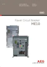
ME10
Brand: AEG Pages: 228

VC AET-100
Brand: VOLTCRAFT Pages: 4

WB015
Brand: Reliance Controls Pages: 2

FEDERAL PACIFIC DST-2
Brand: Reliance electric Pages: 24

LCB2000/2
Brand: Megger Pages: 4

HAF Series
Brand: Hyundai Pages: 28


